
Liquid type identification device

a type identification and liquid technology, applied in the direction of temperature measurement of flowing materials, instruments, material analysis, etc., can solve the problems of engine output efficiency reducing, fuel tank in a car is erroneously replenished with a different type of fuel, and the combustion condition is not optimal for another fuel in some cases, so as to achieve rapid and easy identification of liquids and stable identification

Active Publication Date: 2009-02-24
SAN-A
View PDF10 Cites 5 Cited by
  • Summary
  • Abstract
  • Description
  • Claims
  • Application Information

AI Technical Summary

Benefits of technology

[0024]According to the present invention, a single pulse voltage is applied to the heating body of the liquid type detection unit with indirect heating so as to generate heat and, based on an output of a liquid type detection circuit, the identification calculation unit identifies the liquid to be measured belonging to the hydrocarbon-based liquid or alcohol-based liquid by using the liquid-type-corresponding first voltage value and liquid-type-corresponding second voltage value obtained when the heating body is heated. With the above operation, it is possible to rapidly and easily identify the liquid to be measured.
[0025]In particular, an averaged initial voltage value is used as a voltage value corresponding to the initial temperature of the temperature-sensitive body, an averaged first voltage value is used as a voltage value corresponding to a first temperature of the temperature-sensitive body, an averaged second voltage value is used as a voltage value corresponding to a second temperature of the temperature-sensitive body, a difference between the averaged first voltage value and averaged initial voltage value is used as the liquid-type-corresponding first voltage value, and a difference between the averaged second voltage value and averaged initial voltage value is used as the liquid-type-corresponding second voltage value. With the above configuration, a stable identification can be achieved.
[0026]By determining whether the liquid to be measured is the hydrocarbon-based or alcohol-based liquid using a first calibration curve indicating a relationship between the liquid temperature and liquid-type-corresponding first voltage value based on the liquid temperature-corresponding output value and liquid-type-corresponding first voltage value of the liquid to be measured, and by identifying the liquid to be measured using a second calibration curve indicating a relationship between the liquid temperature and liquid-type-corresponding second voltage value obtained respectively for the hydrocarbon-based liquid and alcohol-based liquid based on the liquid temperature-corresponding output value, liquid-type-corresponding second voltage value, and result of the above determination obtained for the liquid to be measured, more accurate identification of the liquid to be measured can be achieved.

Problems solved by technology

Therefore, even if a combustion condition (air-fuel ratio or amount of fuel injection per unit time) on the internal-combustion engine side is optimally set on the assumption of combustion of one fuel having a given material composition, the combustion condition is not optimal for another fuel in some cases.
When such various types of fuels are sold in the same manner in service station and the like, it becomes likely that a fuel tank in a car is erroneously replenished with a fuel different from a predetermined one.
If such occurs, the engine output efficiency may decrease extremely.

Method used


Image

  • Liquid type identification device
  • Liquid type identification device
  • Liquid type identification device

Examples


Embodiment Construction

[0042]An embodiment of the present invention will be described below with reference to the accompanying drawings.

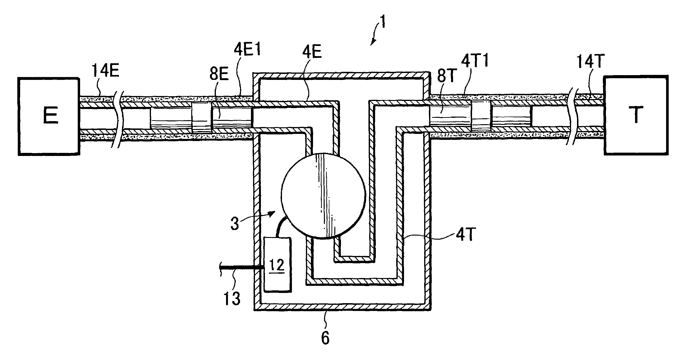
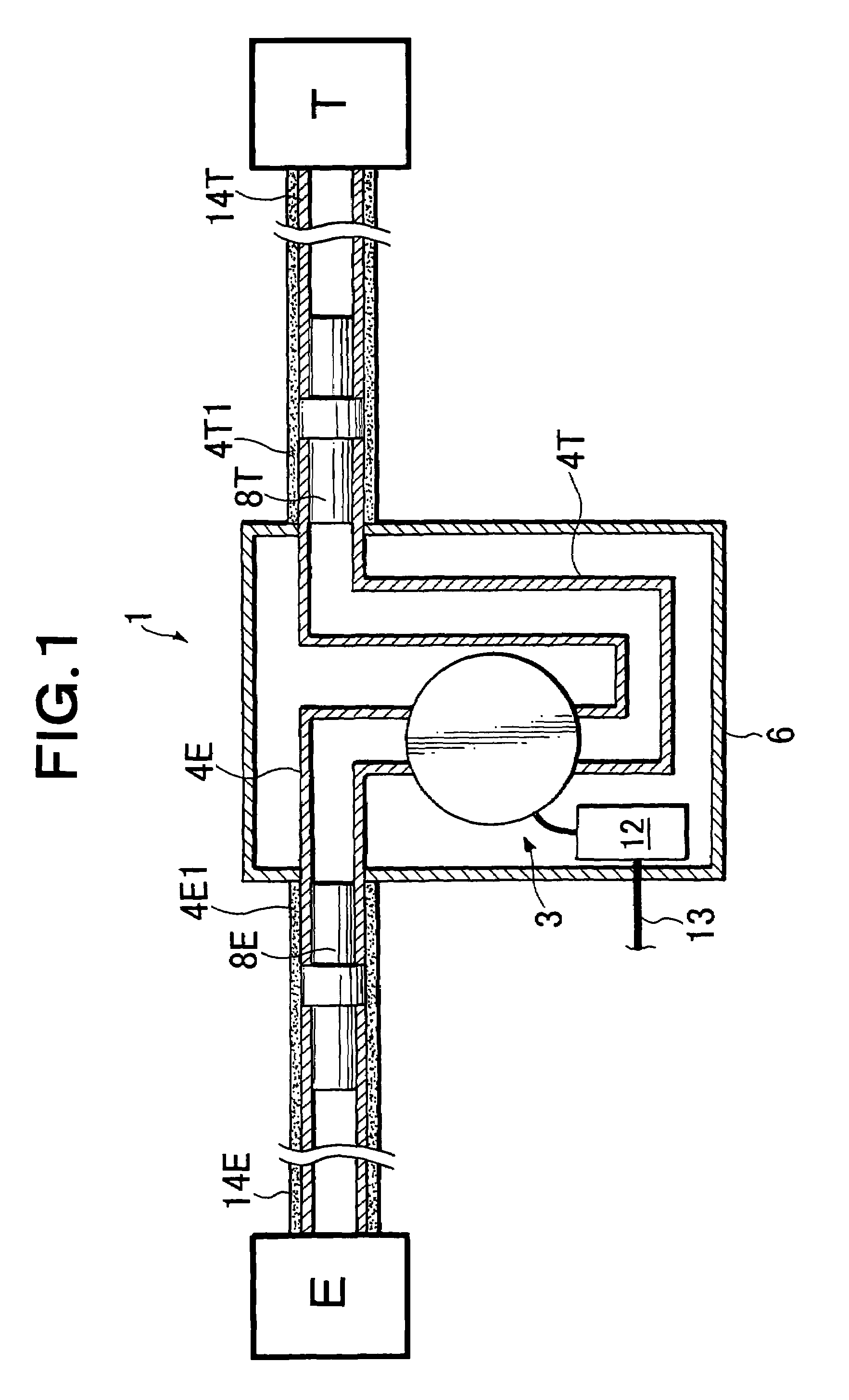
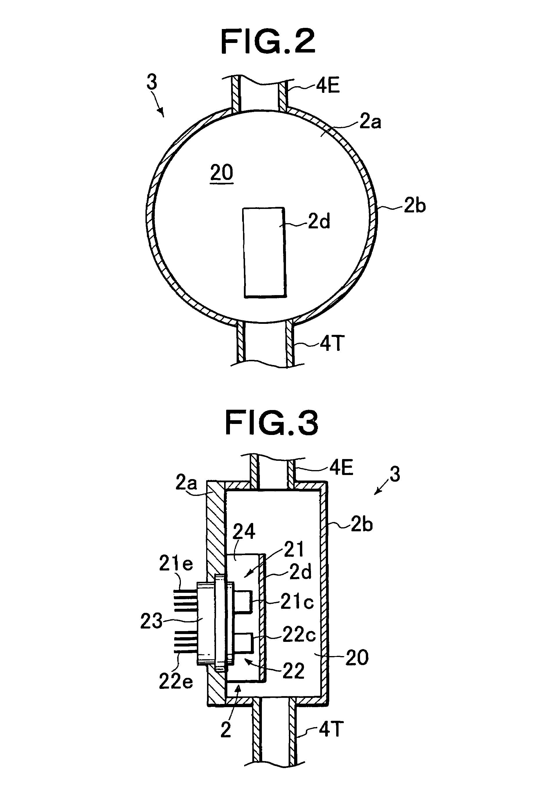
[0043]FIG. 1 is a schematic configuration view showing a use state of an embodiment of a liquid type identification device according to the present invention. FIGS. 2 to 4 are cross-sectional views of the respective portions of the device. In the present embodiment, a supply passage of a liquid (fuel) to be measured supplies the liquid to be measured from a tank of the liquid to an internal-combustion engine. However, the supply passage of liquid to be measured of the present invention is not limited to this, but it may be a passage that supplies a liquid to be measured from a tank to a tank truck or from a large-sized tank to a small-sized tank.

[0044]As shown in FIG. 1, a liquid type identification device 1 for identifying the type of a liquid to be measured is provided in the middle of a supply passage for supplying the liquid to be measured from a tank T for liquid to ...


PUM

PropertyMeasurementUnit
time periodaaaaaaaaaa
timeaaaaaaaaaa
time periodaaaaaaaaaa

Abstract

There is provided an identification device capable of accurately, rapidly, and easily identifying a hydrocarbon-based liquid and alcohol-based liquid. An identification sensor unit (2) is arranged to face a flow passage (20) of a liquid to be measured and includes a liquid type detection unit with indirect heating (21) having a heating body and a temperature-sensitive body, and a liquid temperature detecting unit (22) for detecting the temperature of the liquid to be measured. The identification device further includes an identification calculation unit for applying a single pulse voltage to the heating body of the liquid type detection unit (21) so as to generate heat and identifying the liquid to be measured according to an output of a liquid type detection circuit formed by the temperature-sensitive body of the liquid type detecting unit (21) and the liquid temperature detection unit. The identification calculation unit identifies the liquid to be measured according to a liquid-type-corresponding first voltage value corresponding to a difference between the initial temperature of the temperature-sensitive body when the heating body generates heat and a first temperature at the moment when the a first time has elapsed from the start of application of the single pulse and a liquid-type-corresponding second voltage value corresponding to a difference between the initial temperature of the temperature-sensitive body and a second temperature at the moment when a second time longer than the first time has elapsed from the start of application of the single pulse.

Description

[0001]This application is a 371 of PCT / JP2005 / 000894 filed on Jan. 25, 2005, published on Aug. 11, 2005 under publication number WO 2005 / 073700A1 which claims priority benefits from Japanese Patent Application Number 2004-023645 filed Jan. 30, 2004.TECHNICAL FIELD[0002]The present invention relates to a liquid type identification device which uses thermal properties of liquid to identify the liquid type.BACKGROUND ART[0003]In general, gasoline or gas oil is used in an internal-combustion engine of a car. Such a fuel is a mixture of various hydrocarbons and other materials. In the light of concerns about a future reduction in the output of fossil fuels and in the light of a strong request for a reduction in emission of carbon dioxide in the fight against global warming, it is currently being studied that alcohol (e.g., ethanol or methanol) which is a plant-derived fuel is mixed in the gasoline for the fuel of an internal-combustion engine.[0004]The material composition of such a fuel...

Claims


Application Information

Patent Timeline
Patent Type & Authority Patents(United States)
IPC IPC(8): G01N25/00G01K13/02G01N25/18G01N27/18G01N33/28
CPCG01N27/18G01N33/28
Inventor KAWANISHI, TOSHIAKITAKAHATA, TAKAYUKIYAMAGISHI, KIYOSHI
Owner SAN-A
Learn More