Thread tension device for sewing machine

a tension device and sewing machine technology, applied in sewing apparatus, thin material handling, textiles and paper, etc., can solve the problems of troublesome adjusting operation, troublesome detachment of exterior cover, and high time consumption of adjusting work, so as to achieve quick adjusting work and adjust the tension exerted on the needle thread

Active Publication Date: 2009-02-24
BROTHER KOGYO KK
View PDF17 Cites 2 Cited by
  • Summary
  • Abstract
  • Description
  • Claims
  • Application Information

AI Technical Summary

Benefits of technology

[0009]Therefore, an object of the present disclosure is to provide a thread tension device which can easily and quickly carry out a work for adjusting the magnitude of a reference tension.
[0012]In a case where the thread tension dial assumes, for example, a turning position of dial scale “3” serving as a reference scale, the operator adjusts the spring force of the thread tension spring when the magnitude of the tension exerted on the needle thread differs from the adjustment reference value. In this case, the operator detaches a face plate covering the head of the sewing machine, inserting the distal end of the adjusting tool into the through hole formed in the thread guide assembly. While being engaged with the second adjusting member, the distal end of the adjusting tool is turned so that the second adjusting member is turned, whereupon the first adjusting member is turned with the second adjusting member. As a result, the spring force of the thread tension spring is increased or decreased.
[0013]In the above-described construction, when adjusting the magnitude of the tension at the reference position of the thread tension dial, the operator detaches the face plate covering the head of the sewing machine, inserting the distal end of the adjusting tool into the through hole formed in the thread guide assembly. The first adjusting member can be turned just when the distal end of the adjusting tool is turned while being engaged with the second adjusting member, so that the tension exerted on the needle thread can be adjusted easily and quickly. Furthermore, the adjusting work can be carried out quickly since the tension adjustment is performed by detaching the face plate which can generally be detached more easily than an external cover of the arm.
[0015]In the above-described construction, the distal end of the adjusting tool having been inserted into the through hole of the thread guide assembly is guided by the guide. Accordingly, the distal end of the adjusting tool can reliably be engaged with the engagement recess. Furthermore, the second adjusting member is turned by the mesh engagement of the second gear of the second adjusting member with the first gear of the first adjusting member, whereupon the first adjusting member is turned reliably and easily. Consequently, the tension adjusting work for the needle thread can greatly be simplified.
[0017]In further another embodiment, the flange of the first adjusting member has an outer peripheral surface formed with a knurling, the thread tension device further comprising a leaf spring member having one of two ends engaging the knurling and the other end fixed to the transfer plate. In this construction, the leaf spring and the knurling engage each other. As a result, the first adjusting member having the flange formed with the knurling can be prevented from inadvertent rotation during the sewing operation. Consequently, the tension exerted on the needle thread can reliably be prevented from variation due to rotation of the first adjusting member. Furthermore, the leaf spring and the knurling engage each other. Accordingly, rotation of a small concavo-convex portion of the knurling oscillates the leaf spring member upon turn of the first adjusting member in the tension adjusting work. As a result, the turn of the first adjusting member produces clicks. When confirming the clicks, the operator can easily determine turn of the first adjusting member.
[0019]In the above-described construction, the thread guide assembly of the thread tension device is exposed upon detachment of the face plate. Accordingly, when the tension of the needle thread is adjusted, the face plate is detached so that the through hole of the thread guide assembly is exposed. Thus, the tension exerted on the needle thread can be adjusted when only the face plate which can be detached easier is detached without detachment of the outer cover. Consequently, the adjusting work can be carried out quickly.

Problems solved by technology

As a result, detachment of the exterior cover is troublesome.
Moreover, the thread tension adjusting member needs to be manually turned, whereupon a troublesome adjusting operation is necessitated.
As a result, there is a problem that the adjusting work necessitates much time.

Method used


Image

  • Thread tension device for sewing machine
  • Thread tension device for sewing machine
  • Thread tension device for sewing machine

Examples


Embodiment Construction

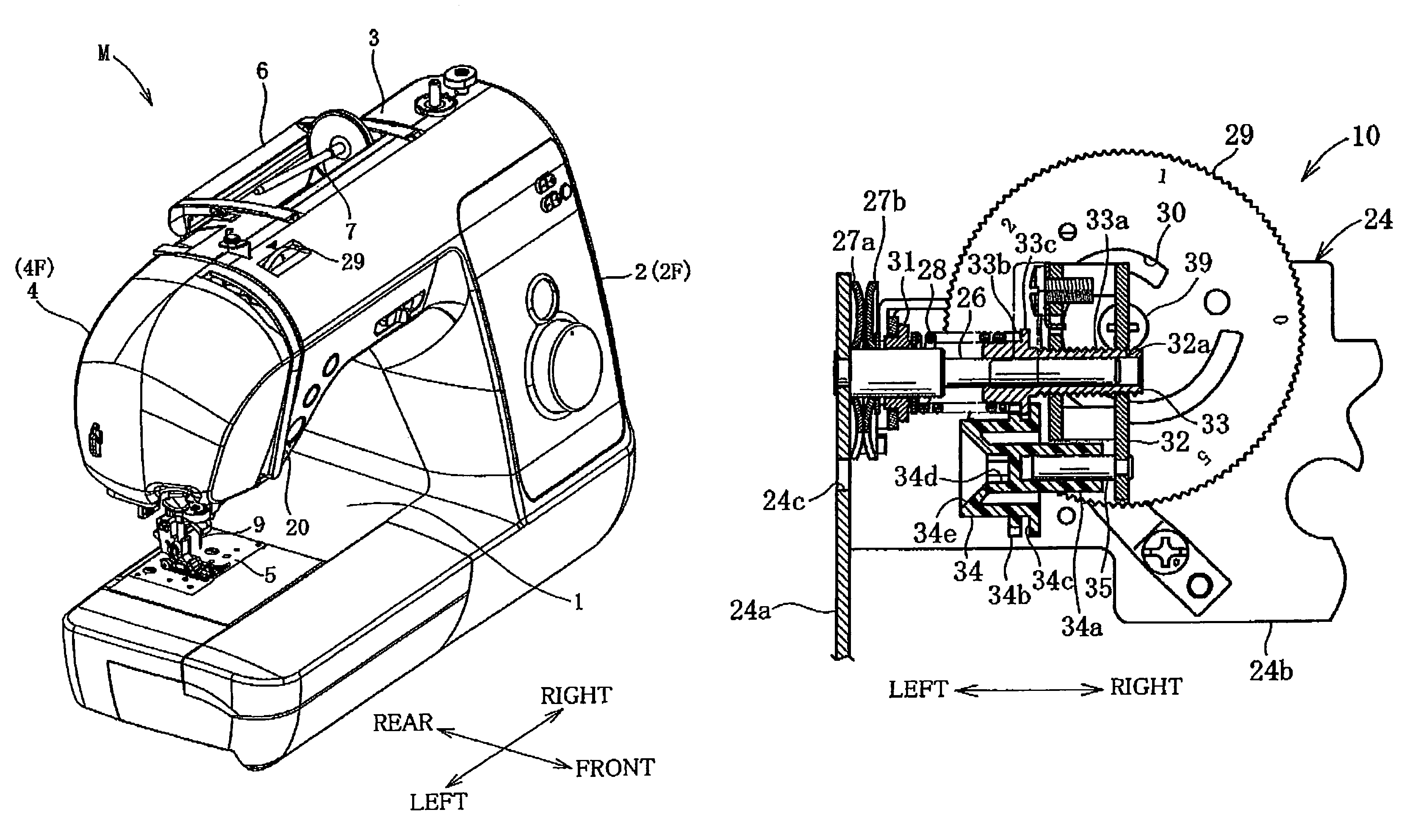
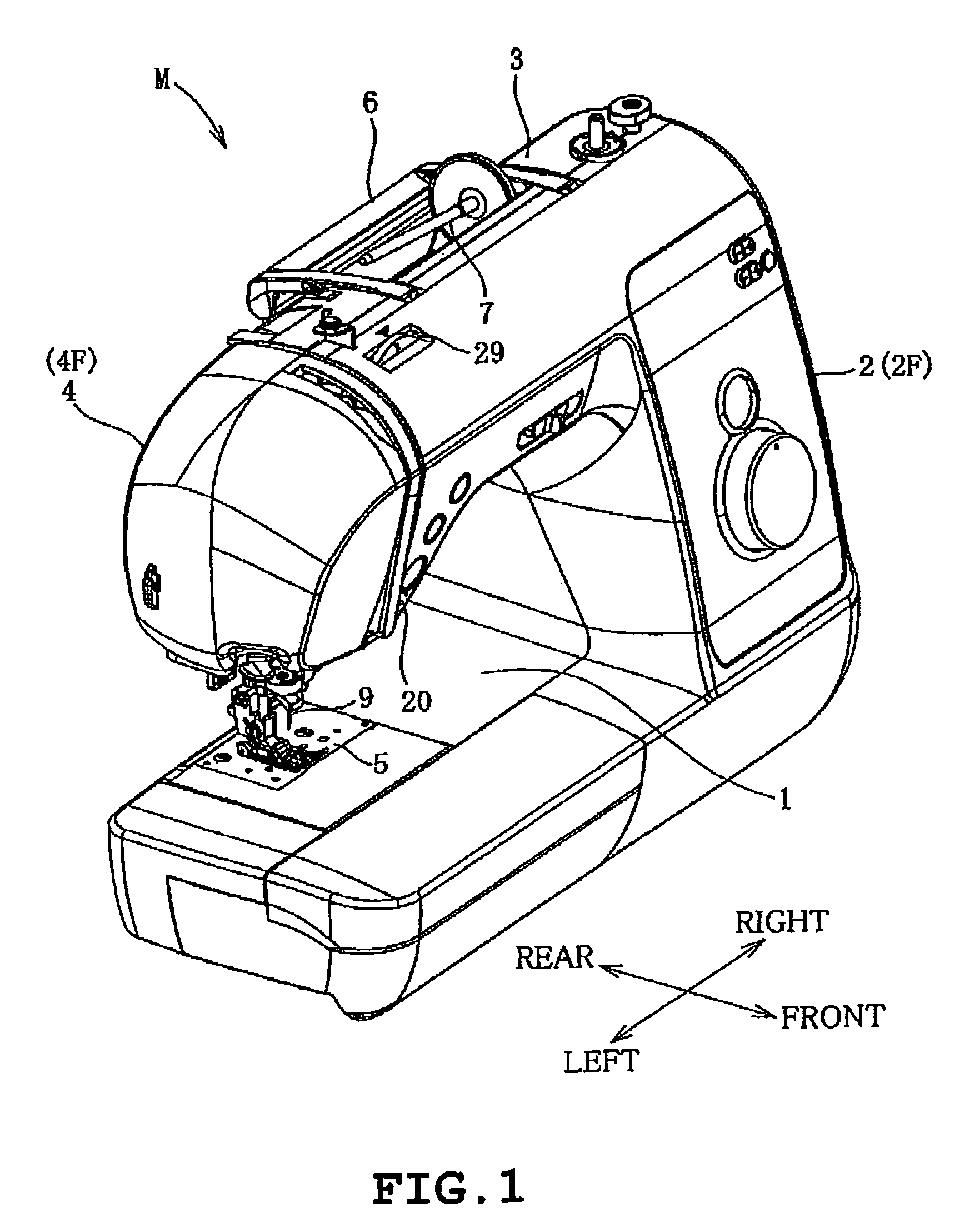
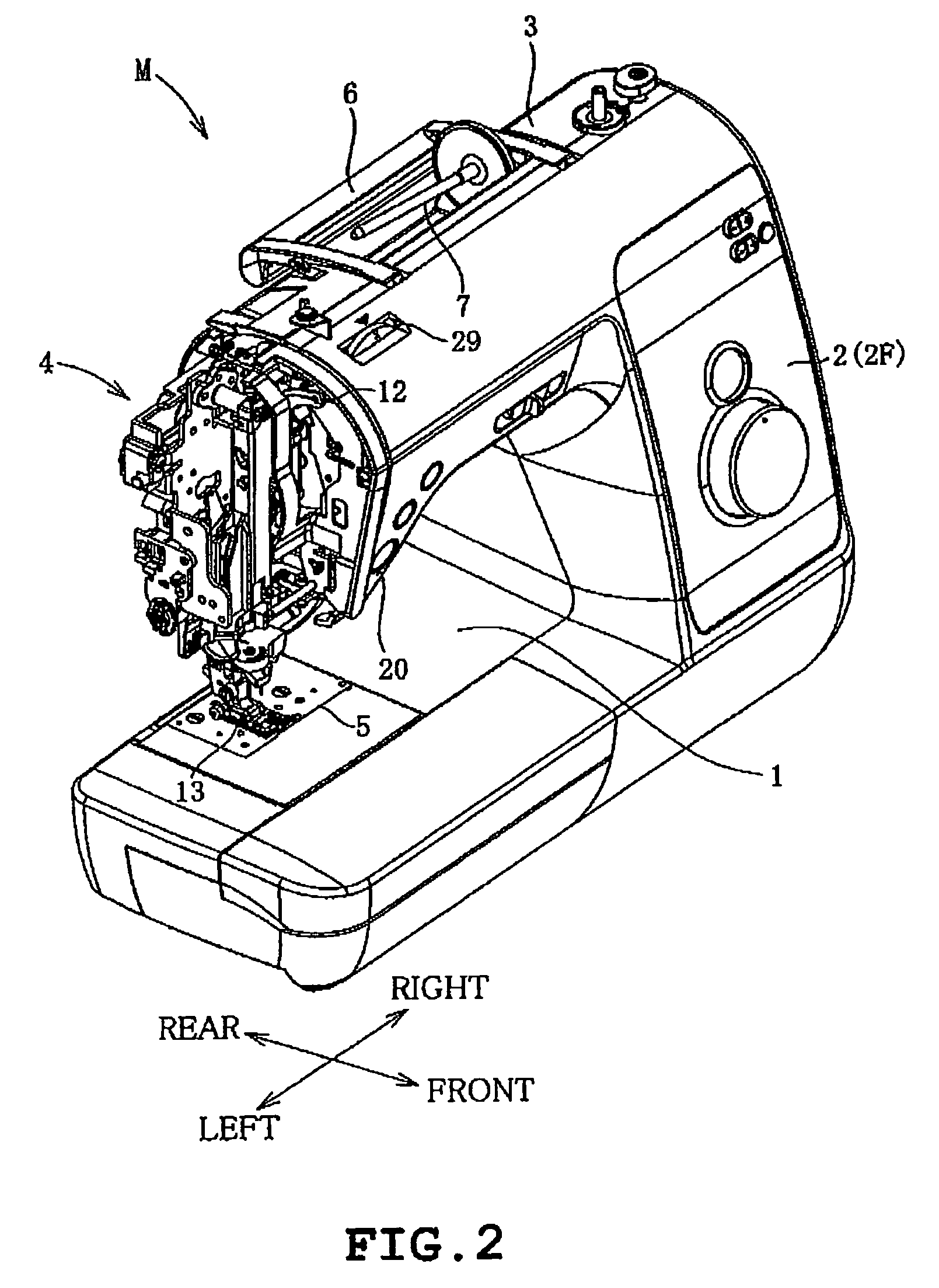
[0032]One embodiment will be described with reference to the accompanying drawings. Referring to FIGS. 1 and 2, an electronic sewing machine M with which the thread tension device of the embodiment is provided is shown. The electronic sewing machine M includes a bed 1, a pillar 2, an arm 3 and a head 4. The pillar 2 stands from a right end of the bed 2, and the arm 3 extends leftward from an upper end of the pillar 2 so as to be opposed to the bed 1. The head 4 is provided on a left part of the arm 3. The pillar 2 and the arm 3 have respective fronts covered with an outer cover 2F. A thread tension dial 29 which will be described later is partially exposed from an upper left part of the arm 3 relative to the outer cover 2F, whereupon the thread tension dial 29 is manually operable. The head 4 is covered with a curved face plate 4F. FIG. 2 shows the electronic sewing machine M with the face plate 4F being detached. A needle plate 5 is provided on the bed 1. A thread cutting mechanism...


PUM


Abstract

A thread tension device includes paired thread tension discs holding a needle thread, a thread tension spring biasing one of the discs toward the other, a thread tension dial adjusting a tension exerted on the needle thread, a spring force adjusting cam formed in the thread tension dial, a transfer plate following the cam so as to be capable of adjusting the spring force, and a first adjusting member threadingly engaged with the transfer plate to receive one end of the thread tension spring, a thread guide assembly having a through hole formed so that the adjusting tool is insertable into the through hole, and a second adjusting member rotatably mounted on the transfer plate and engageable with the distal end of the adjusting tool inserted into the through hole so as to be rotatable with the tool, thereby rotating the first adjusting member by rotation of the tool.

Description

CROSS-REFERENCE TO RELATED APPLICATIONS[0001]This application is based on and claims the benefit of priority from the prior Japanese Patent Application No. 2007-108186, filed on Apr. 17, 2007, the entire contents of which are incorporated herein by reference.BACKGROUND[0002]1. Field[0003]The present invention relates to a sewing machine, and more particularly to a thread tension device therefor including a thread tension dial which is manually turned by an operator so that a tension applied to a needle thread clamped between a pair of thread tension discs is adjusted.[0004]2. Related Art[0005]Conventional lockstitch sewing machines are provided with a thread tension device in a sewing arm. The thread tension device includes a thread tension dial for adjusting the strength of tension applied to a needle thread. The thread tension dial has an upper end partially exposed outward from an upper part of the sewing arm, so as to be externally operable. When workpiece cloth is to be sewn, a...

Claims


Application Information

Patent Timeline
Patent Type & Authority Patents(United States)
IPC IPC(8): D05B47/00D05B73/00
CPCD05B47/00
Inventor FUKAO, HIROAKI
Owner BROTHER KOGYO KK
Why Eureka
Try Eureka