Method and apparatus for monitoring conveyor belts

a technology of conveyor belts and monitoring devices, applied in the direction of alarms, instruments, conveyor parts, etc., can solve the problems of mail sorting equipment becoming increasingly complex, improper machine operation, damage to mail pieces and/or machine damage,

Active Publication Date: 2009-02-24
KÖRBER SUPPLY CHAIN LLC
View PDF12 Cites 56 Cited by
  • Summary
  • Abstract
  • Description
  • Claims
  • Application Information

AI Technical Summary

Problems solved by technology

Due to the tremendous volume of mail processed daily in the United States and other countries, mail sorting equipment has become increasingly complex.
Action of any unbalanced force may change the dynamic configuration of the belt and mail and may eventually lead to improper functioning of the machine, damage of the mail pieces and / or damage to the machine.
The fundamental structural properties and the harsh dynamics of the process environment make the belts prone to wear and, in many cases, failure.
For example, letter and mail processing machines have interlocked doors and covers such that runtime access is prohibited for safety and security reasons.
Many areas within mail handling machines and systems cannot be viewed during operation.
Additionally, in large material handling systems, it is simply not practical to provide operator access to all areas of the system.
Determining the condition of belts used in mail sorting and handling machines can therefore be an involved, cumbersome and eventually expensive process.
In addition they examine the belt during operation for improper tracking, scalloping, improper tension, bad alignment etc.
Since mail sorting machines may have several hundred conveyor belts, many of which are hidden behind panels or in hard to access areas, the task of inspecting the belts is time consuming and sometimes ineffective.
Further, some modes of belt failure have no advance visual indications.
As a result, conveyor belts fail during operation reducing the reliability of the machine.
A fundamental issue in high volume processing operations is the conflict between the desire to operate a machine and the need to halt the machine to perform needed belt replacement, maintenance and troubleshooting functions.
There is an element of risk that if a machine is taken down for troubleshooting and repair, it may not be available for the next processing cycle.
In many cases, troubleshooting the problem requires more time than the actual repair, once the problem is known.

Method used


Image

  • Method and apparatus for monitoring conveyor belts
  • Method and apparatus for monitoring conveyor belts
  • Method and apparatus for monitoring conveyor belts

Examples


Embodiment Construction

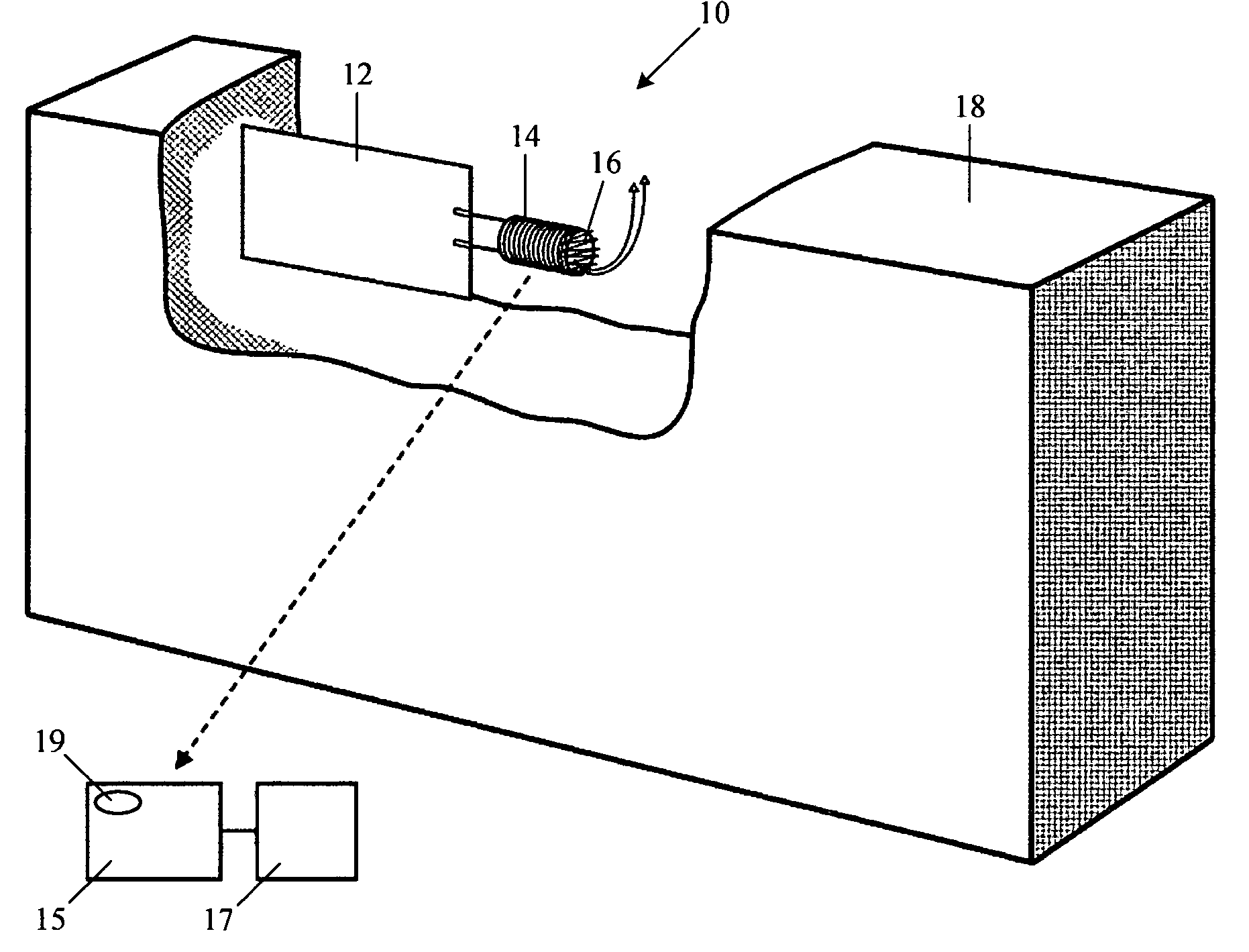
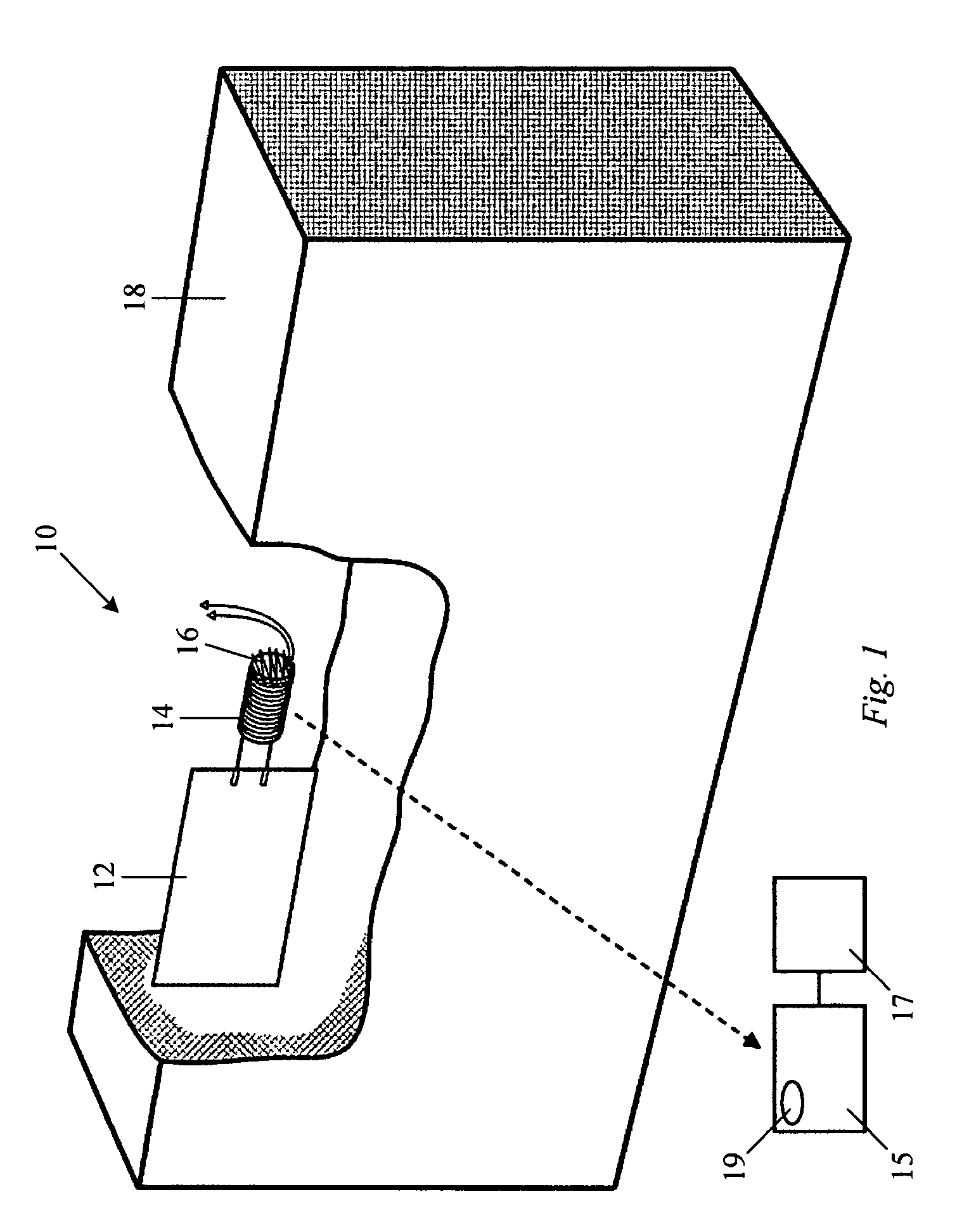
[0017]Referring to FIG. 1, an imbedded belt cycle counter 10 includes a piezoelectric bend sensor 12, an induction coil 14 and an antenna 16. Bend sensor 12 is embedded in conveyor belt 18 such that when the section of the belt 18 carrying imbedded sensor 12 bends or deflects as it passes around a pulley or roller, an electrical potential is generated by piezoelectric bend sensor 12. The electric potential across the bend sensor creates a current in induction coil 14 which is coupled to antenna 16 which in turn generates a corresponding RF signal. The signal is received by a locally mounted receiver 15 and monitor 17 including a counter (hardware or software function) that counts and stores the number of signals received from sensor 12. When the recorded number of cycles reaches a predetermined number as indicated on a screen display 19 or other suitable means, belt 18 is scheduled for inspection, maintenance or replacement in accordance with a predetermined maintenance scheme.

[0018...


PUM


Abstract

A smart belt consists of a standard belt with an embedded sensor capable of wireless communication or visual indicators to notify maintenance for a need for maintenance or replacement. The sensor measures material properties, cycles of operation etc. using a self energizing power source. When the belt requires replacement or maintenance a mode of indication will notify proper personnel.

Description

[0001]This application is a conversion and claims priority of U.S. Provisional Application No. 60 / 816,167, filed Jun. 23, 2006.TECHNICAL FIELD[0002]The invention relates to sensing devices and systems designed to be installed in or on a conveyor belt or related components for detecting conditions and / or collecting data regarding the conveyor and associated equipment.BACKGROUND OF THE INVENTION[0003]Due to the tremendous volume of mail processed daily in the United States and other countries, mail sorting equipment has become increasingly complex. Sophisticated scanning equipment along with computer controlled high speed conveying and sorting machines are used to process ever increasing volumes of postcards, letters, magazines, parcels and other types of mail. The dynamics of mail processing is the outcome of the interplay of various driving forces that must be controlled. The mail undergoes action of various forces from one point in a machine to another in a number of steps. Action ...

Claims


Application Information

Patent Timeline
Patent Type & Authority Patents(United States)
IPC IPC(8): B65G43/00
CPCB65G43/02
Inventor STOLYAR, MARKKELLY, DANIELDWIVEDI, RAJEEV
Owner KÖRBER SUPPLY CHAIN LLC
Why Eureka
Try Eureka