Optical fiber fusion splicer and method for estimating a shape of beam discharged by the optical fiber fusion splicer

a technology of optical fiber fusion and splicer, which is applied in the direction of optics, instruments, optical light guides, etc., can solve the problems of large current for the main arc discharge, affecting various conditions, etc., and achieves the effect of accurate estimation and simplifying the maintenance of the discharge beam

Inactive Publication Date: 2009-02-24
THE FUJIKURA CABLE WORKS LTD
View PDF15 Cites 10 Cited by
  • Summary
  • Abstract
  • Description
  • Claims
  • Application Information

AI Technical Summary

Benefits of technology

[0019]The arc discharge is generated in a cylindrical shape as if to connect the discharge electrodes. Because the image of the discharge beam is obtained by picking up an image of this cylindrical positive column, the central axis thereof normally matches a straight line between the discharge electrodes. However, if the discharge electrodes deteriorate and become worn or have dust or the like adhering thereto, then this causes the discharge beam to be slanted or distorted. Therefore, if only one line were used to estimate the brightness distribution on the image of the discharge beam, it would not be possible to notice the distortions in the shape. For this reason, as is described above, in the image of the discharge beam, a plurality of lines substantially at right angles to the direct line between the discharge electrodes are set such that each line is at a different position from the others in a rectilinear direction between the discharge electrodes and the brightness distribution is estimated on each of these lines. Namely, a plural number of lines are used for measuring the brightness distribution and the position of each line is made different from the position of each of the other lines. As a result, even if the discharge beam is slanted or distorted, the shape thereof can be accurately estimated. This enables the center of the heating by the arc discharge to be accurately estimated and abnormal states such as a deterioration of the discharge electrodes or foreign matter such as dust being adhered to the discharge electrodes to be detected, which can be utilized when maintenance is carried out, thereby simplifying the maintenance of the discharge beam or the like.

Problems solved by technology

Because the main arc discharge is performed in order to heat the abutment portion, the current for the main arc discharge is affected by various conditions and is generally quite large.

Method used


Image

  • Optical fiber fusion splicer and method for estimating a shape of beam discharged by the optical fiber fusion splicer
  • Optical fiber fusion splicer and method for estimating a shape of beam discharged by the optical fiber fusion splicer
  • Optical fiber fusion splicer and method for estimating a shape of beam discharged by the optical fiber fusion splicer

Examples


Embodiment Construction

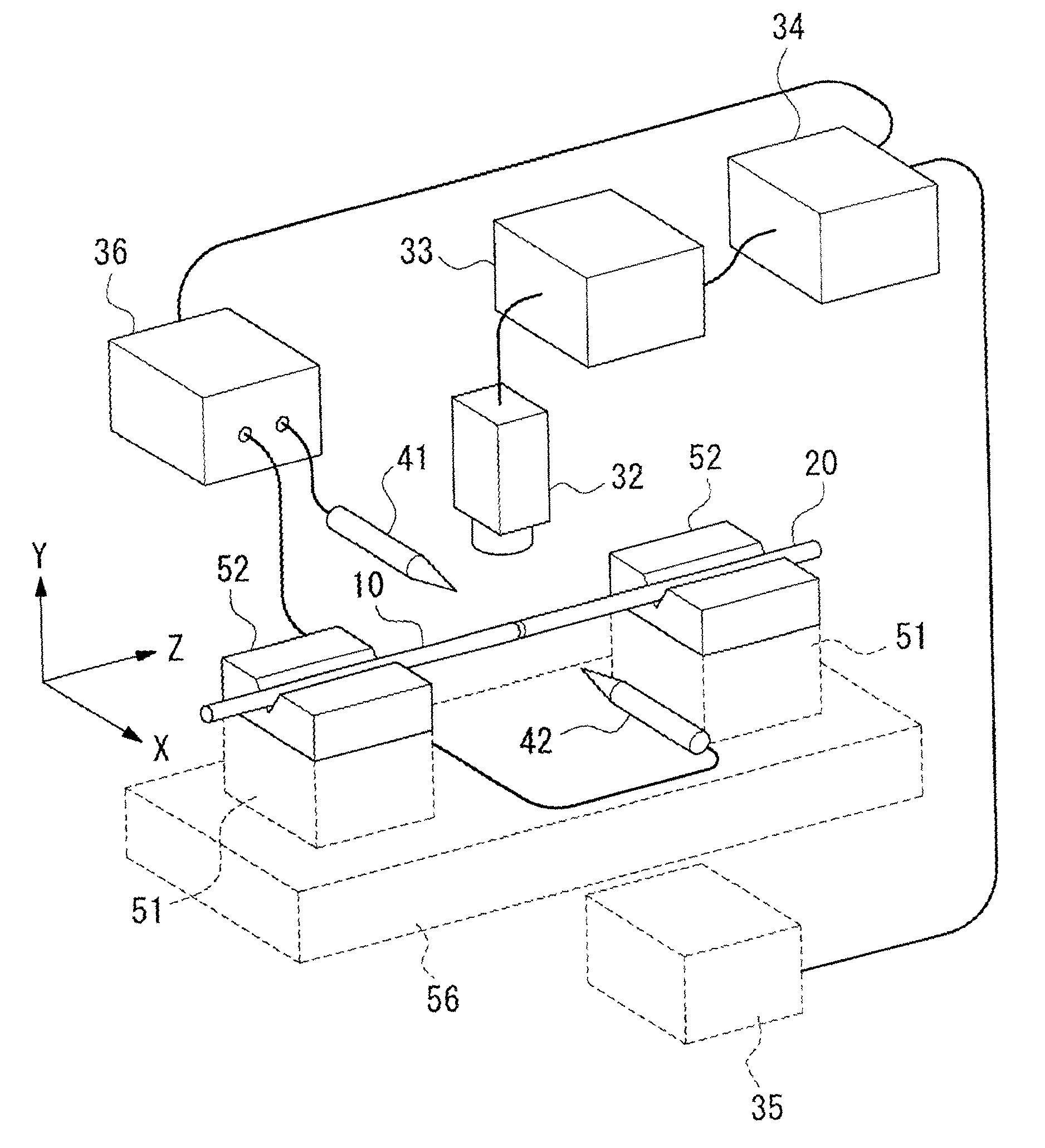
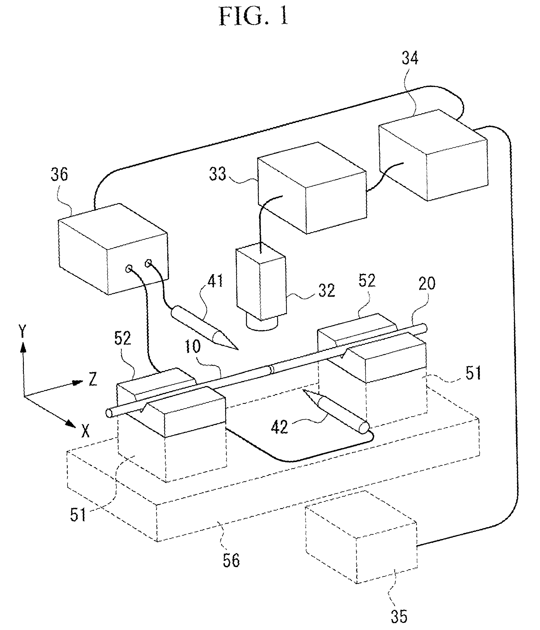
[0025]A detailed description will be given of an embodiment of an present invention with reference made to the accompanying drawings. FIG. 1 is an upper perspective view schematically showing the optical fiber fusion splicer according to an embodiment of the present invention. In FIG. 1, V groove blocks 52 (setting means) are used for setting in position each of two optical fibers 10 and 20 that are to be spliced, and are mounted on top of moving blocks 51. The moving blocks 51 are capable of movement in the three axial directions X, Y, and Z. Note here that the axial direction (horizontal direction) of the optical fibers 10 and 20 is taken as the Z direction, a horizontal direction at a right angle to the axis of the optical fibers 10 and 20 is taken as the X direction, and a vertical direction at a right angle to the axis of the optical fibers 10 and 20 is taken as the Y direction. The moving blocks 51 are mounted on a base 56 and are moved on the base 56 by a drive device 35 in t...


PUM


Abstract

The present invention is provided for fusion splicing optical fibers with low splice loss even when a shape of a discharge beam for the splicing is distorted. In the present invention, a preliminary discharge is performed with the optical fibers outside a discharge area and an image of the discharge beam thereof is picked up. Based on this image, brightness distributions of the discharge beam are estimated on a plurality of lines in a Z direction that are set in different positions in an X direction, and a discharge center of the beam is found from the plurality of brightness distributions. Then, the abutment portion of the optical fibers is positioned at the discharge center, and a main discharge is performed so as to fusion splice the distal ends of the optical fibers.

Description

BACKGROUND OF THE INVENTION[0001]1. Field of the Invention[0002]The present invention relates to an optical fiber fusion splicer that abuts the respective end surfaces of two optical fibers that are to be spliced against each other and fusion splices these optical fibers by heating the abutment portion by arc discharge, and to a method for estimating a shape of a beam which is discharged by the optical fiber fusion splicer.[0003]2. Description of the Related Art[0004]Optical fiber fusion splicers first abut the respective end surfaces of two optical fibers that are to be spliced against each other and then fusion the two end surfaces by heating the abutment portion by arc discharge, resulting in the two optical fibers becoming fusion spliced. In this optical fiber fusion splicer, in order to be able to always make a stable splicing with little splice loss, it is essential that both of the end surfaces of the two optical fibers being spliced are heated uniformly. Namely, it is necess...

Claims


Application Information

Patent Timeline
Patent Type & Authority Patents(United States)
IPC IPC(8): G02B6/255
CPCG02B6/2551
Inventor OZAWA, KOJITAYA, HIROYUKI
Owner THE FUJIKURA CABLE WORKS LTD
Why Eureka
Try Eureka