Fan bracket and heat dissipation apparatus incorporating the same

a technology of fan brackets and heat dissipation apparatuses, which is applied in the direction of light and heating apparatus, machines/engines, liquid fuel engines, etc., can solve the problems of increasing the cost, increasing the cost, and complicating the manufacture of the heat sink

Active Publication Date: 2009-02-24
CHAMP TECH OPTICAL FOSHAN
View PDF25 Cites 16 Cited by
  • Summary
  • Abstract
  • Description
  • Claims
  • Application Information

AI Technical Summary

Benefits of technology

[0005]In the heat dissipation apparatus, a fan bracket is used to attach the heat dissipating fan onto the heat sink. A conventional fan bracket includes a housing, four arm portions extending downwardly from the housing, and a fixing portion extending upwardly from the housing. The heat dissipating fan is fixed to the fan bracket via the fixing portion. The heat sink is attached to the fan bracket via the arm portions. Each of the arm portions includes a hook extending inwardly from a free end thereof. The heat sink defines four concaves for receiving the hooks therein so as to attach the heat sink onto the fan bracket. Thus, there is a need for carving the concaves in the heat sink during manufacturing of the heat sink. This complicates the manufacture of the heat sink and increases the cost thereof. In addition, there is a need for providing additional fasteners to attach the heat sink to the heat producing component. Also, engaging structures need to be arranged on the heat sink to engage with the fasteners, which further complicates the manufacture of the heat sink and increases the cost thereof. Therefore, there is a need to provide a fan bracket which can mount a heat sink onto the heat producing component without requiring the addition of a complicated structure on the heat sink.

Problems solved by technology

This complicates the manufacture of the heat sink and increases the cost thereof.
Also, engaging structures need to be arranged on the heat sink to engage with the fasteners, which further complicates the manufacture of the heat sink and increases the cost thereof.

Method used


Image

  • Fan bracket and heat dissipation apparatus incorporating the same
  • Fan bracket and heat dissipation apparatus incorporating the same
  • Fan bracket and heat dissipation apparatus incorporating the same

Examples


Embodiment Construction

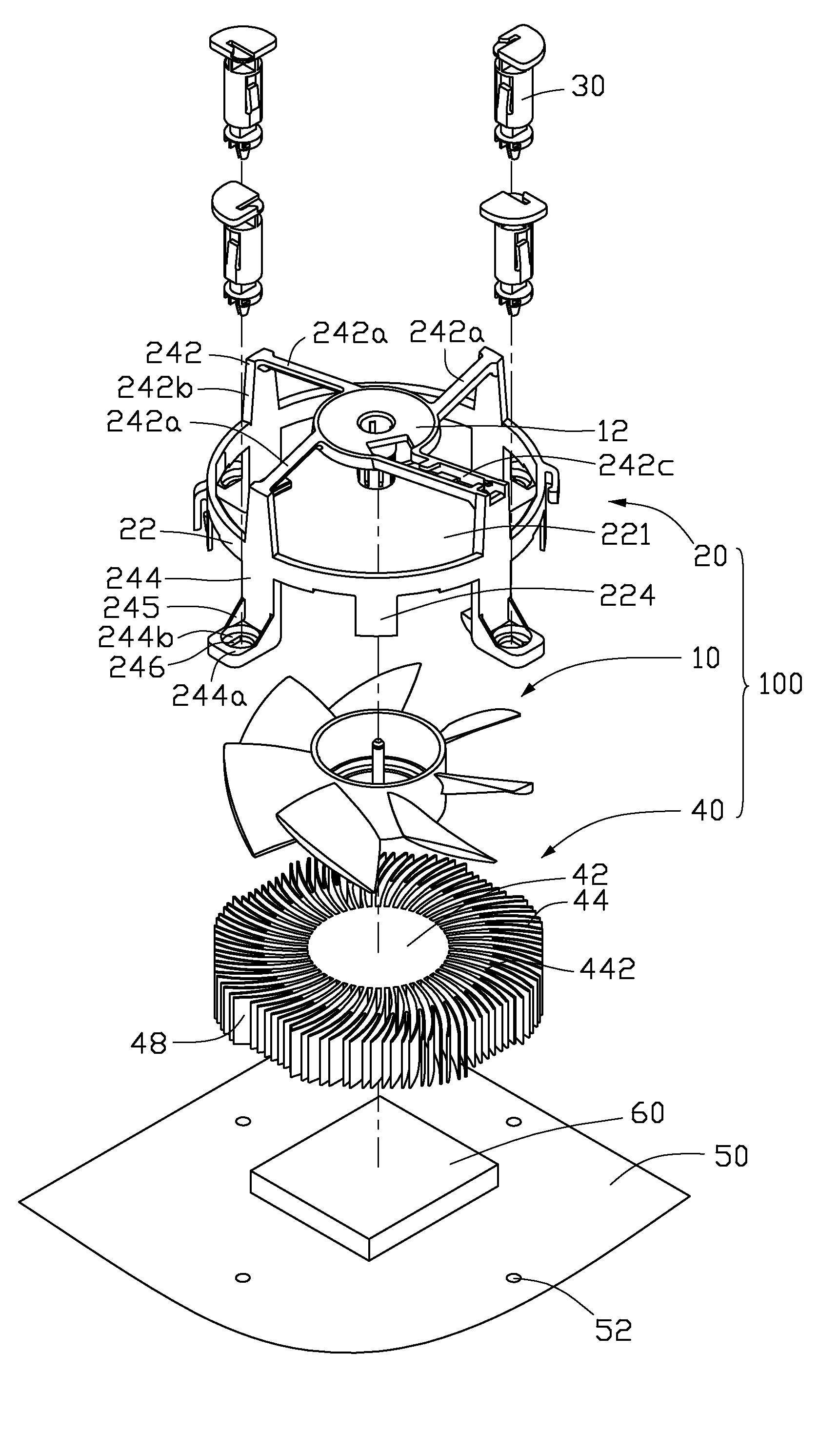
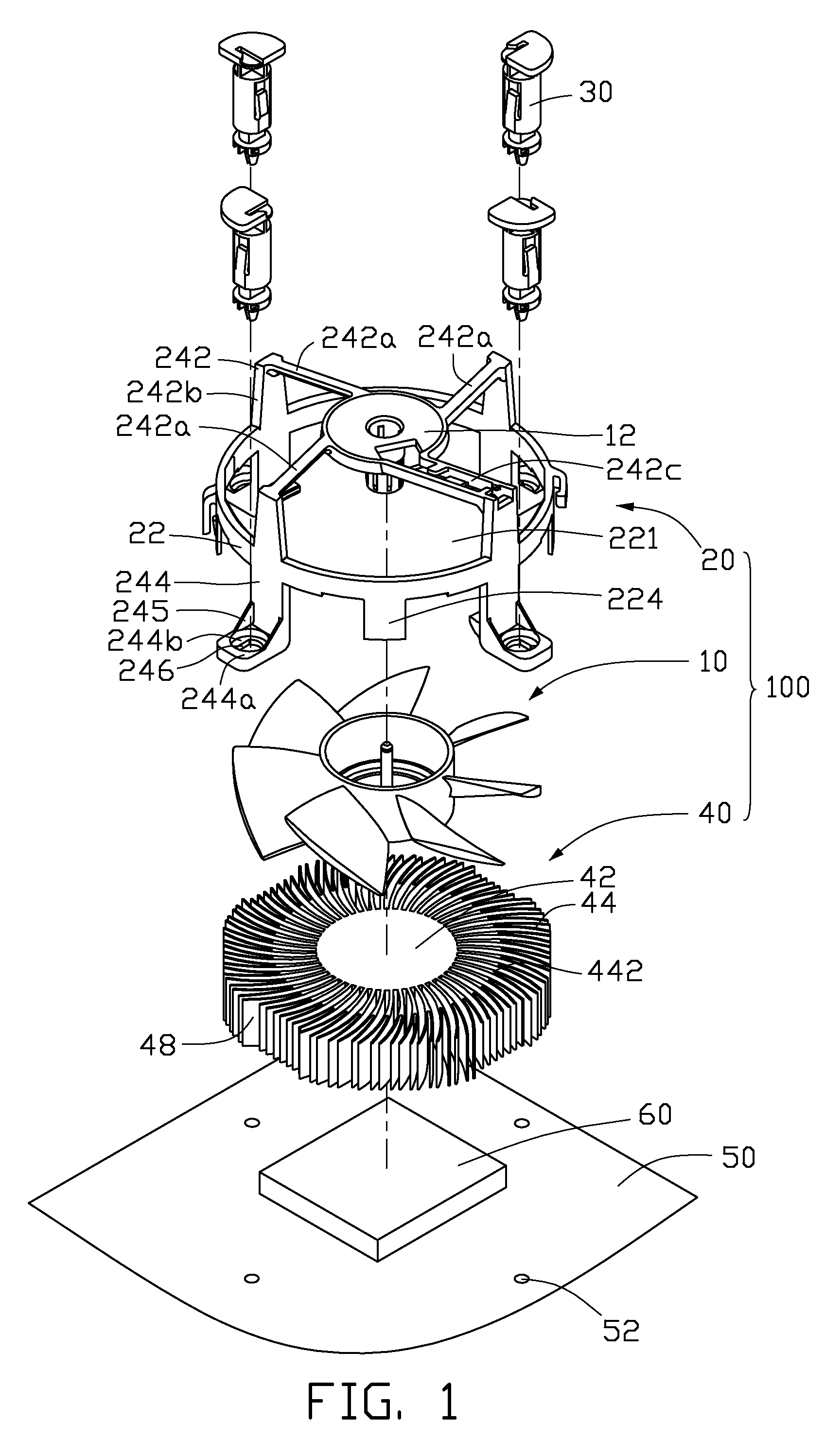
[0013]Referring to FIG. 1, a heat dissipation apparatus 100 according to a preferred embodiment of the present invention is shown. The heat dissipation apparatus 100 is mounted to a printed circuit board 50 with a heat source 60 such as a CPU arranged thereon via four fasteners 30. The heat dissipation apparatus 100 includes a fan bracket 20, a heat dissipating fan 10 and a heat sink 40. The heat dissipating fan 10 and the heat sink 40 are respectively mounted to top and bottom portions of the fan bracket 20. The heat sink 40 contacts with the heat source 60 for absorbing heat thereform. The heat dissipating fan 10 generates an airflow flowing through the heat sink 40 to take away heat thereform.

[0014]The fan bracket 20 includes a substantially circular housing 22, four arm portions 244 and four positioning portions 224 extending downwardly from the housing 22, and a support portion 242 extending upwardly from the housing 22. The housing 22 defines a circular hole 221 in a middle po...


PUM


Abstract

A heat dissipation apparatus (100) includes a fan bracket (20), a fan (10) and a heat sink (40). The fan bracket includes a housing (22), a support portion (242) extending from the housing, and a plurality of arm portions (244) extending from the housing in a direction opposite to the support portion. Each of the arm portions includes an engaging portion (244a) extending outwardly therefrom, engaging with a fastener (30) to mount the heat dissipation apparatus to a printed circuit board (50). At least two arm portions each include a hook (244c) extending inwardly therefrom. The fan is attached to the support portion of the fan bracket. The heat sink is held between the arm portions of the fan bracket with a bottom surface of the heat sink engaging with the hooks.

Description

BACKGROUND OF THE INVENTION[0001]1. Field of the Invention[0002]The present invention relates to fan brackets, and more particularly to a fan bracket which can mount a heat dissipating apparatus onto a heat producing component without requiring the addition of a complicated structure on the heat dissipating apparatus.[0003]2. Description of Related Art[0004]Heat dissipation apparatus are traditionally used in micro-electronics to help transfer of heat from heat producing components. The heat dissipation apparatus includes a heat sink absorbing heat from the heat producing component, and a heat dissipating fan generating an airflow which flows through the heat sink to take away heat therefrom.[0005]In the heat dissipation apparatus, a fan bracket is used to attach the heat dissipating fan onto the heat sink. A conventional fan bracket includes a housing, four arm portions extending downwardly from the housing, and a fixing portion extending upwardly from the housing. The heat dissipa...

Claims


Application Information

Patent Timeline
Patent Type & Authority Patents(United States)
IPC IPC(8): H05K7/20H01L23/36
CPCF04D29/582F04D29/601F04D29/668H01L23/4093H01L23/467H01L2924/0002H01L2924/00
Inventor CHANG, YUH-CHINGZHAO, YONG-QIANGCAO, MING-KUN
Owner CHAMP TECH OPTICAL FOSHAN
Why Eureka
Try Eureka