Transmission circuit and communication apparatus employing the same

a transmission circuit and communication circuit technology, applied in the field of transmission circuits, can solve the problems of increasing power consumption of transmission circuits, difficult to achieve desired transmission signals sb>0/b>, and large circuit scale of conventional transmission circuits b>700/b>, and achieve high linearity and high efficiency

Active Publication Date: 2009-02-24
III HLDG 12 LLC
View PDF16 Cites 14 Cited by
  • Summary
  • Abstract
  • Description
  • Claims
  • Application Information

AI Technical Summary

Benefits of technology

[0018]Therefore, an object of the present invention is to provide a small-size transmission circuit which outputs a transmission signal having high linearity independently of the magnitude of the output power, and operates with high efficiency, and a communication apparatus employing the transmission circuit.
[0033]Also, the computation section, when the magnitude of the amplitude component of the input data is smaller than the predetermined amplitude threshold value, outputs an amplitude signal obtained by multiplying the predetermined amplitude threshold value by a predetermined constant, a first phase signal obtained by shifting the phase component of the input data by a predetermined phase in one direction, and a second phase signal obtained by shifting the phase component of the input data by a predetermined phase in another direction. Therefore, the transmission circuit, when the magnitude of the amplitude component of the input data is smaller than the predetermined amplitude threshold value, can combine the first modulated signal and the second modulated signal whose magnitudes are the same and whose phases are different from each other, and output the combined signal as the transmission signal. Thereby, the transmission circuit can output a transmission signal having high linearity with high efficiency, independently of the magnitude of an output power varying depending on the magnitude of the amplitude component of the input data.
[0034]Also, the transmission circuit does not branch output signals of the first amplitude modulation section and the second amplitude modulation section, thereby making it possible to suppress a loss accompanying signal branching, resulting in a reduction in power consumption for a transmission circuit.
[0035]Also, the transmission circuit changes the magnitude of the predetermined amplitude threshold value so that the magnitude of the predetermined amplitude threshold value has inverse characteristics with respect to the magnitude of the output power indicated by the input transmission power information, and amplifies the amplitude signal output by the computation section using a gain which has direct characteristics with respect to the magnitude of the output power indicated by the transmission power information. Thereby, the transmission circuit can output a transmission signal having high linearity with high efficiency even when the magnitude of the output power indicated by the transmission power information varies.
[0036]Also, according to the communication apparatus of the present invention, by employing the above-described transmission circuit, a small size and a high-efficiency operation can be achieved while securing the accuracy of an output signal over a wide bandwidth.

Problems solved by technology

However, in the conventional transmission circuit 600, since the transmission signal S0 is generated by combining the output signal S1 and the output signal S2, it is difficult to achieve the desired transmission signal S0 if the output signal S1 and the output signal S2 include a phase error or an amplitude error.
Therefore, the conventional transmission circuit 700 unavoidably has a large circuit scale.
Also, in the conventional transmission circuit 700, since the output of each of the amplifier 602 and the amplifier 603 is branched, the branching causes a loss, so that the power consumption of the transmission circuit increases.

Method used


Image

  • Transmission circuit and communication apparatus employing the same
  • Transmission circuit and communication apparatus employing the same
  • Transmission circuit and communication apparatus employing the same

Examples


first embodiment

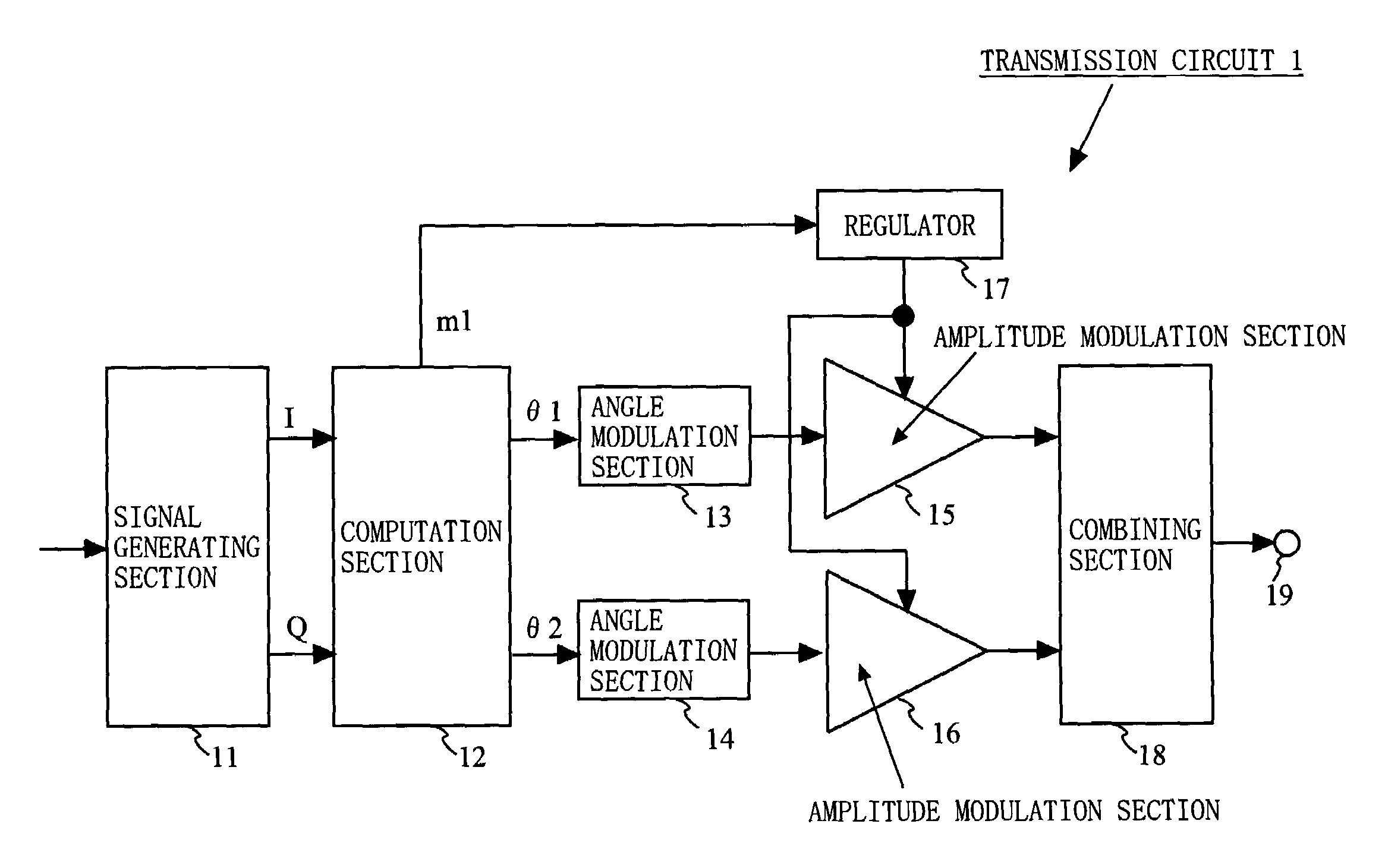
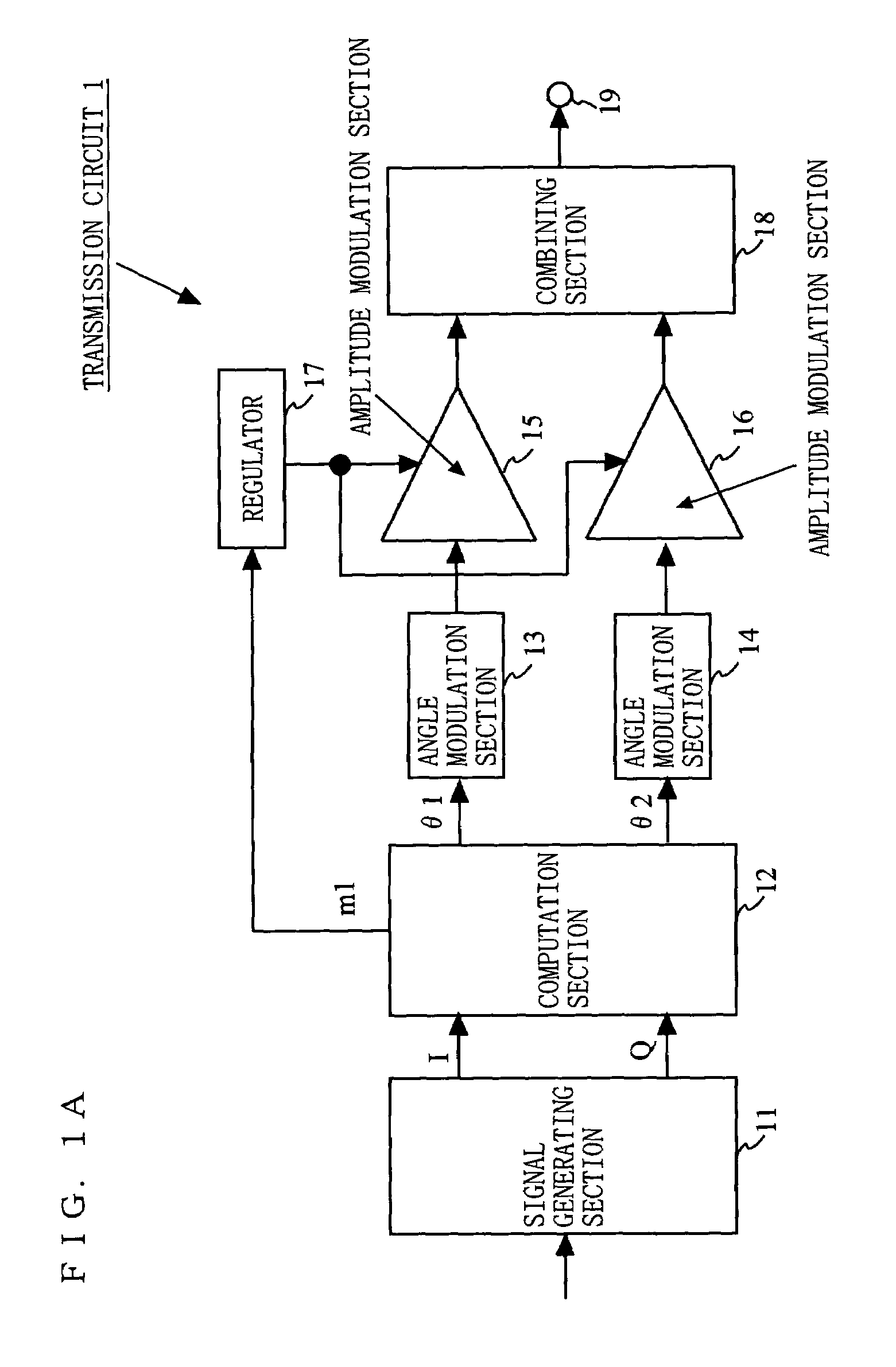
[0070]FIG. 1A is a block diagram illustrating an exemplary configuration of a transmission circuit 1 according to a first embodiment of the present invention. In FIG. 1A, the transmission circuit 1 comprises a signal generating section 11, a computation section 12, an angle modulation section 13, an angle modulation section 14, an amplitude modulation section 15, an amplitude modulation section 16, a regulator 17, a combining section 18, and an output terminal 19.

[0071]The signal generating section 11 modulates input data to generate data in a predetermined format. Specifically, the signal generating section 11 generates an in-phase signal and a quadrature-phase signal (hereinafter, such an in-phase signal and a quadrature-phase signal will be referred to as “I and Q signals”), which are quadrature signals. Note that the signal generating section 11 may generate, for example, data including an amplitude component and a phase component as the data in the predetermined format. The I a...

second embodiment

[0103]FIG. 11 is a block diagram illustrating an exemplary configuration of a transmission circuit 2 according to a second embodiment of the present invention. In FIG. 11, the transmission circuit 2 is different from the transmission circuit 1 of the first embodiment in that a variable gain amplification section 20 is further provided. Also, an operation of a computation section 22 is different from that of the first embodiment. FIG. 12 is a diagram illustrating a signal used in each section of the transmission circuit 2. Hereinafter, an operation of the transmission circuit 2 will be described with reference to FIG. 12.

[0104]Transmission power information P indicating a magnitude of an output power of a transmission signal every a slot time is input to the transmission circuit 2 (see (a) of FIG. 12). The computation section 22 changes the magnitude of the predetermined amplitude threshold value 2m0 every the slot time based on the input transmission power information P. Specificall...

third embodiment

[0111]FIG. 15 is a block diagram illustrating an exemplary configuration of a transmission circuit 3 according to a third embodiment of the present invention. In FIG. 15, the transmission circuit 3 comprises a signal generating section 11, a computation section 32, an angle modulation section 13, an angle modulation section 14, an amplitude modulation section 15, an amplitude modulation section 16, a regulator 27, a combining section 18, and an output terminal 19. The transmission circuit 3 is different from the transmission circuit 1 of the first embodiment in operations of the computation section 32 and the regulator 27. Note that the regulator 27 is similar to the regulator 17d of the second embodiment which has been described with reference to FIG. 14. Hereinafter, an operation of the transmission circuit 3 of the third embodiment of the present invention will be described, mainly focusing on the computation section 32.

[0112]FIG. 16 is a flowchart of an exemplary operation of th...


PUM


Abstract

A small-size transmission circuit is provided which outputs a transmission signal having high linearity independently of a magnitude of an output power, and operates with high efficiency. A signal generating section generates quadrature data based on input data. A computation section compares an amplitude component of the quadrature data with a predetermined amplitude threshold value, and outputs an amplitude signal, a first phase signal, and a second phase signal. A regulator outputs a voltage controlled depending on the amplitude signal. An angle modulation section and an angle modulation section angle-modulate the phase signal to output first and second angle-modulated signals. An amplitude modulation section and an amplitude modulation section amplitude-modulate the first and second angle-modulated signals using a voltage controlled depending on the amplitude signal to output the angle-modulated and amplitude-modulated signals as a first modulated signal and a second modulated signal. A combining section combines the first and second modulated signals to output a transmission signal.

Description

BACKGROUND OF THE INVENTION[0001]1. Field of the Invention[0002]The present invention relates to a transmission circuit for use in a communication apparatus for mobile telephony, wireless LAN, or the like. More particularly, the present invention relates to a small-size transmission circuit which outputs a transmission signal having high linearity independently of a magnitude of an output power and operates with high efficiency, and a communication apparatus employing the transmission circuit.[0003]2. Description of the Background Art[0004]There is a demand for a communication apparatus for mobile telephony, wireless LAN, or the like which can secure the linearity of a transmission signal and operate with low power consumption no matter whether it operates within a large or small power. In such a communication apparatus, a small-size transmission circuit is employed which outputs a transmission signal having high linearity independently of a magnitude of the output power and operate...

Claims


Application Information

Patent Timeline
Patent Type & Authority Patents(United States)
IPC IPC(8): H04B1/02H04B1/04
CPCH04L27/361H04L27/368
Inventor MATSUURA, TORUISHIDA, KAORU
Owner III HLDG 12 LLC
Why Eureka
Try Eureka