Radius measuring tool

a technology of radius and measuring tool, which is applied in the direction of measuring devices, measuring gauges, instruments, etc., can solve the problems of difficult use, difficult conversion tables or calculations, and difficulty in measuring tubular stock inventory,

Active Publication Date: 2009-03-03
WALTZ JR STANLEY J
View PDF8 Cites 5 Cited by
  • Summary
  • Abstract
  • Description
  • Claims
  • Application Information

AI Technical Summary

Benefits of technology

[0011]A tool for measuring the radius of a circularly curved surface provides a generally rectilinear body defining a V notch having an apex and an angulated wedge track spacedly adjacent the apex. A wedge movable along the wedge track and across the V notch intersects a bisector of the V notch at an angle. Opposing angulated sides of the V notch and a measuring edge of the wedge simultaneously contact the circumference of the circular curve at three equally spaced apart positions. Measuring indicia on the body adjacent the wedge track allows determination of the movement of the wedge along the wedge track. The distance the wedge moves is equal to the radius of the circular curve.
[0015]a further object to provide a radius measuring tool that provides precise and accurate measurement of the radius of a curve.
[0016]a further object to provide a radius measuring tool that does not require calculations or use of conversion tables to obtain a radial measurement.
[0022]a still further object to provide such a radius measuring tool that is of new and novel design, of rugged and durable nature, of simple and economic manufacture and one that is otherwise well suited to the uses and purposes for which it is intended.

Problems solved by technology

While this method can be accurate, it requires simultaneous access to opposing sides of the article which may not always be accessible.
For example, partially buried pipes do not normally permit access to opposing sides of the pipe, and measuring an inventory of tubular stock is often hampered by the lack of access to opposing sides of the tubular stock.
Various diameter and radius measuring tools are available, but they are generally complex, difficult to use and require conversion tables or calculations to generate a useable measurement.
Yoke type radius measuring devices have disadvantages as well.
Unfortunately, such devices are unable to measure many articles because the curve to be measured will not fit within the yoke.
Yoke type devices defining notches greater than about 60 degrees are not conducive to probe movement and when the probe movement is minimal, an accurate measurement may not be possible.
Such minimal probe travel from the base to the curve requires that any delineations between measuring indicia on the probe be closely spaced leading to difficult reading and interpretation.
Further, yoke type devices often require an operator to perform mathematical calculations to convert the distance the probe moves into a usable measurement.

Method used


Image

  • Radius measuring tool
  • Radius measuring tool
  • Radius measuring tool

Examples


Embodiment Construction

[0038]As used herein, the term “front”, its derivatives, and grammatical equivalents refers to the planar portion of my radius measuring tool that is generally closest to a user. The term “back”, its derivatives, and grammatical equivalents refers to the planar portion of my radius measuring tool that is generally opposite the user. The term “outer”, its derivatives, and grammatical equivalents refers to an elongate end portion of the radius measuring tool as opposed to a laterally medial portion of the radius measuring tool. The term “radius” is intended in its broadest sense to be in a straight line from a center of a circular curve to the curvature thereabout.

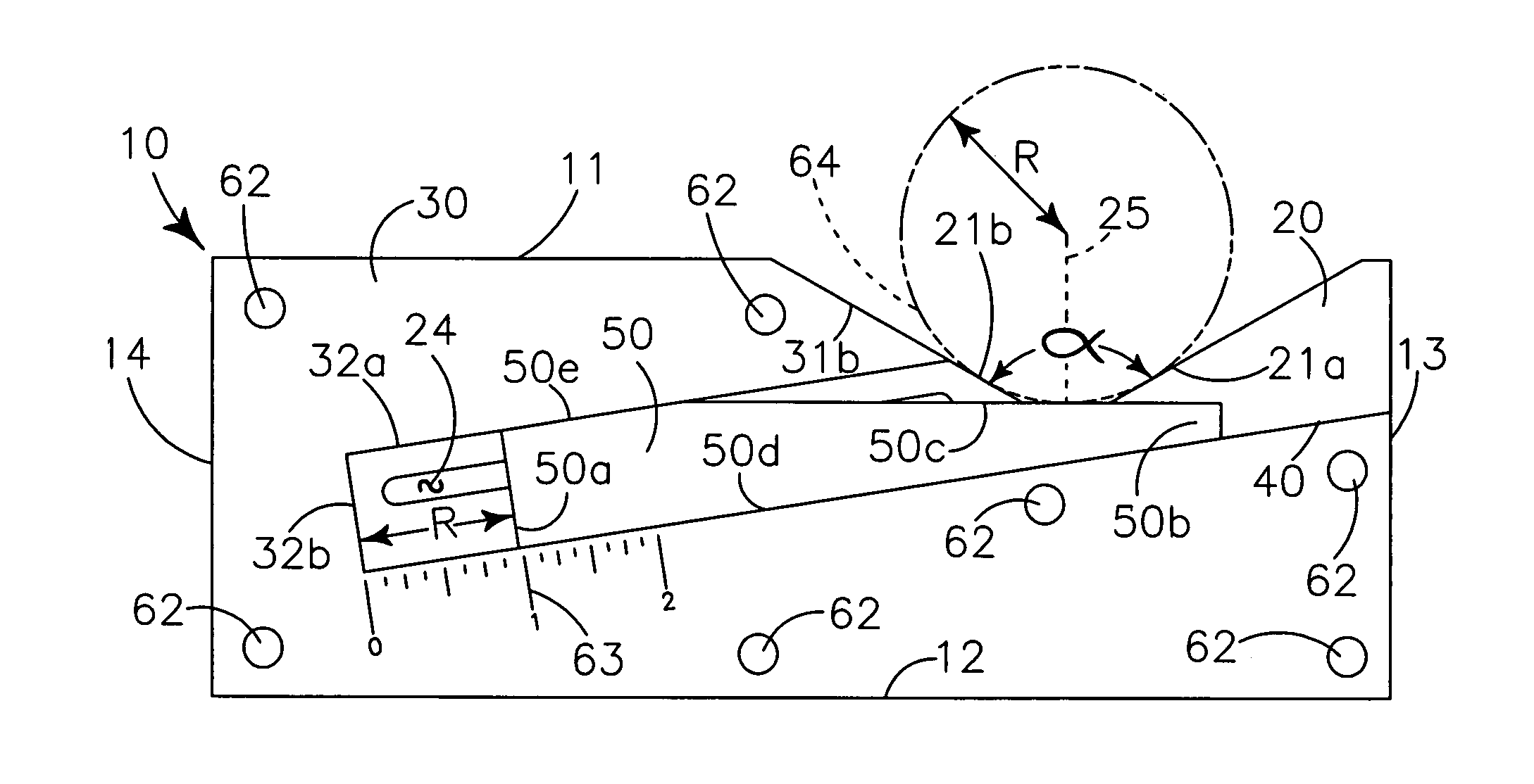
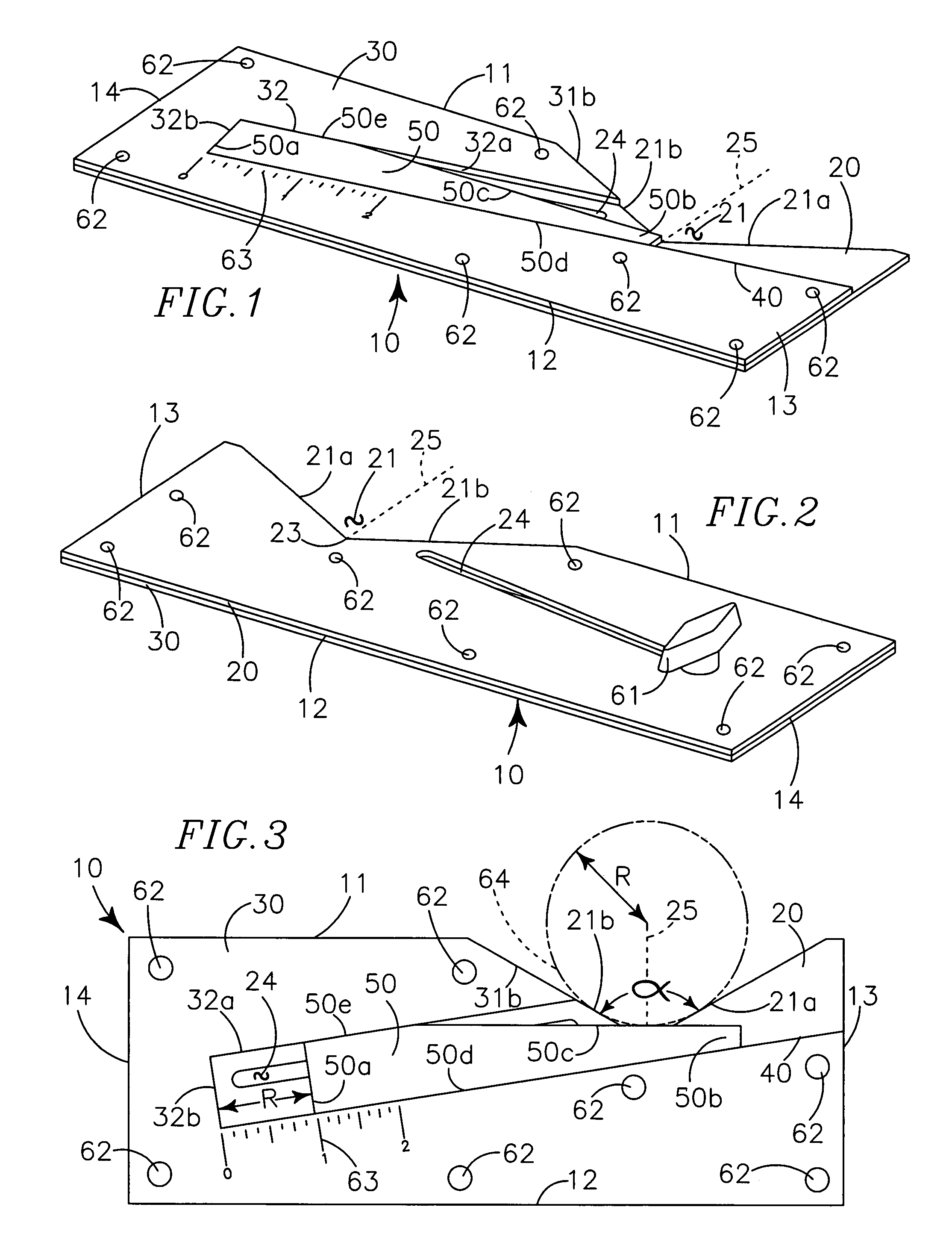
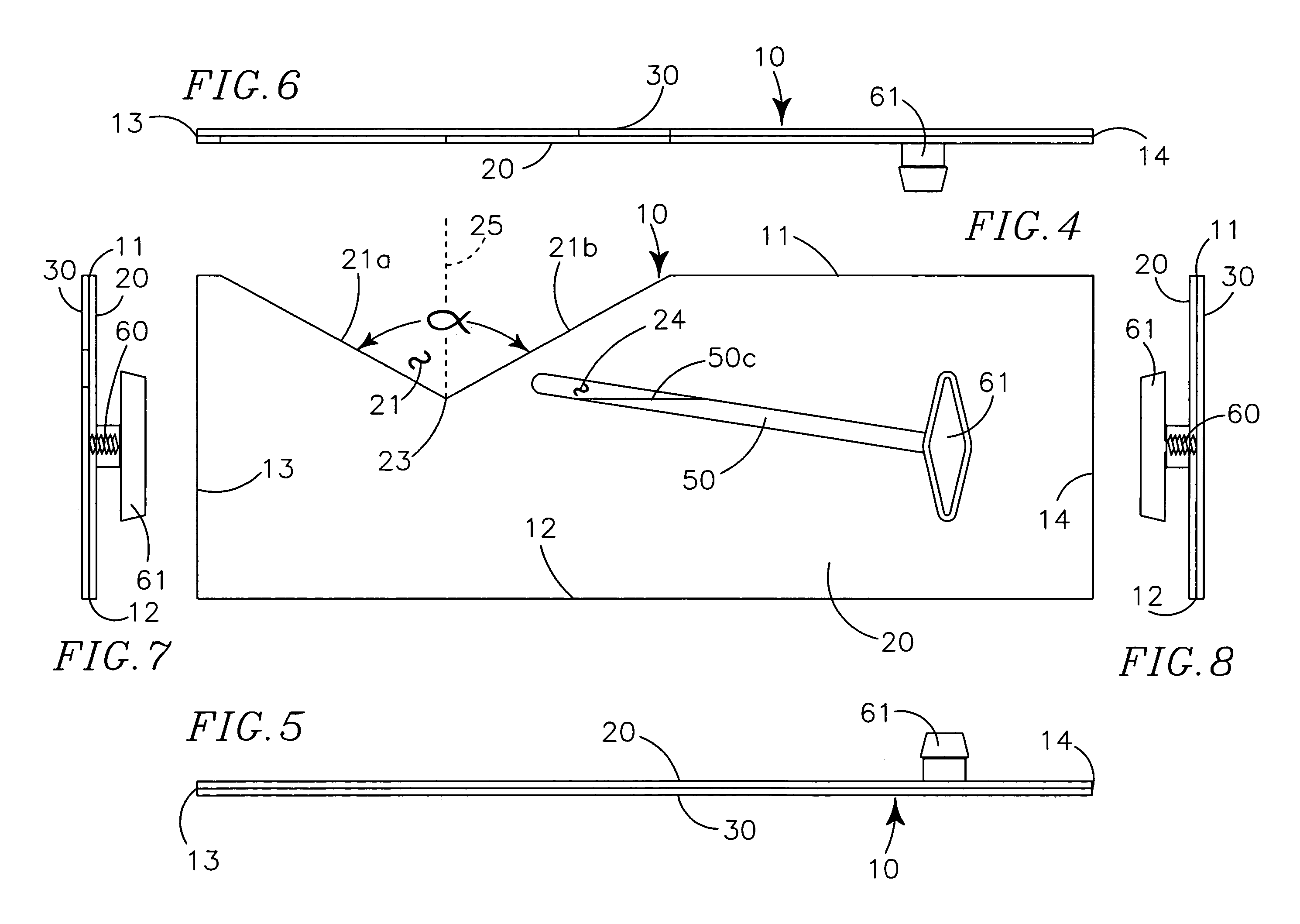
[0039]My radius measuring tool provides a body 10 defining a V notch 21 and an angulated guide track 40 carrying a wedge 50 movable across the V notch 21.

[0040]The body 10 is preferably made of a rigid durable material, such as steel, and is generally rectilinear having an upper edge portion 11, a lower edge portion 12, a fi...


PUM


Abstract

A tool for measuring an object having a circularly curved surface provides a generally rectilinear body defining a V notch having two converging sides meeting at an apex and an angulated wedge track. A wedge movable along the wedge track and across the V notch intersects a bisector of the V notch at an angle other than perpendicular. Sides of the V notch and a measuring edge of the wedge simultaneously contact the circular curve at three equally spaced apart positions along the circumference of the circular curve. Measuring indicia on the body adjacent the wedge track allows determination of the lateral movement of the wedge along the wedge track. The distance the wedge moves on the wedge track is equal to the radius of the circular curve.

Description

RELATED APPLICATIONS[0001]There are no applications related hereto heretofore filed in this or in any foreign country.FIELD OF INVENTION[0002]This invention relates to geometrical instruments, and more particularly to tools for measuring the radius of a circular curve.BACKGROUND AND DESCRIPTION OF PRIOR ART[0003]The radius of curvature of an article is commonly measured by direct measurement of the article's diameter, using a micrometer or similar device. Such devices typically measure the distance between two components contacting the article on diametrically opposing sides, using either mechanical or electronic means. The measured distance is then divided in half to provide the radius of the article.[0004]While this method can be accurate, it requires simultaneous access to opposing sides of the article which may not always be accessible. For example, partially buried pipes do not normally permit access to opposing sides of the pipe, and measuring an inventory of tubular stock is ...

Claims


Application Information

Patent Timeline
Patent Type & Authority Patents(United States)
IPC IPC(8): G01B3/38
CPCG01B3/04G01B3/20G01B5/213
Inventor WALTZ, JR., STANLEY J.
Owner WALTZ JR STANLEY J
Why Eureka
Try Eureka