Photonic pressure sensor device and methods of use thereof

a sensor device and photonic pressure technology, applied in the field of optical sensors, can solve the problems of interference light beam and light beam interference, and achieve the effects of convenient use, convenient portability and precise and accurate measurement of photon radiation pressur

Active Publication Date: 2019-12-31
MICATU
View PDF5 Cites 0 Cited by
  • Summary
  • Abstract
  • Description
  • Claims
  • Application Information

AI Technical Summary

Benefits of technology

[0015]The present technology describes a photonic sensor device and methods of monitoring and measuring photonic pressure that have significant advantages over currently available technologies. The technology advantageously allows for precise and accurate measurement of photon radiation pressure by interferometrically interrogating the induced mechanical motion of a cantilevered optical element through fast sampling of a direct optical modulation signal. The devices of the present technology are advantageously portable, easy to use, and can be utilized to measure photonic pressure in a simple manner over a large dynamic range
[0016]Advantages of the current invention include the simplicity of the power measuring device, and its ability to transduce photon pressure and radiation force into mechanical motion that is sensed using a modulated optical analog power signal. The device requires no electronics or electrical activity in the sensor head making it immune to electromagnetic (EM) and radio-frequency (RF) interference.
[0017]The device of the current technology provides a monolithic optical element that provides a direct conversion of photon pressure into mechanical motion, along with a cavity for interferometric detection of the mechanical displacement. These attributes provide the device with a high level of sensitivity and precision, at least an order of magnitude better than currently available laser power measurement methods, as well as a wide dynamic range. Additionally, the devices and methods of the present technology provide extremely fast response times limited only by data-acquisition, sampling, processor speeds, and high-frequency characterization of transient laser power fluctuations. The sensitivity will be maintained throughout a wide bandwidth from low to laser fluctuation frequencies, as opposed to current methods that degrade rapidly in performance at higher frequencies.

Problems solved by technology

The change in the position of the etalon causes interference of the light within the etalon resulting in an interference light beam.
A light source is optically coupled to the etalon to provide a light beam to the etalon, wherein the change in the position of the etalon causes interference of the light within the etalon resulting in an interference light beam.

Method used


Image

  • Photonic pressure sensor device and methods of use thereof
  • Photonic pressure sensor device and methods of use thereof
  • Photonic pressure sensor device and methods of use thereof

Examples


Embodiment Construction

[0023]The present technology relates to photonic pressure sensor devices and methods of use thereof.

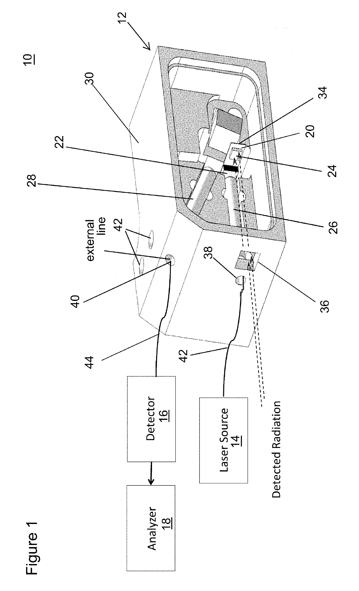
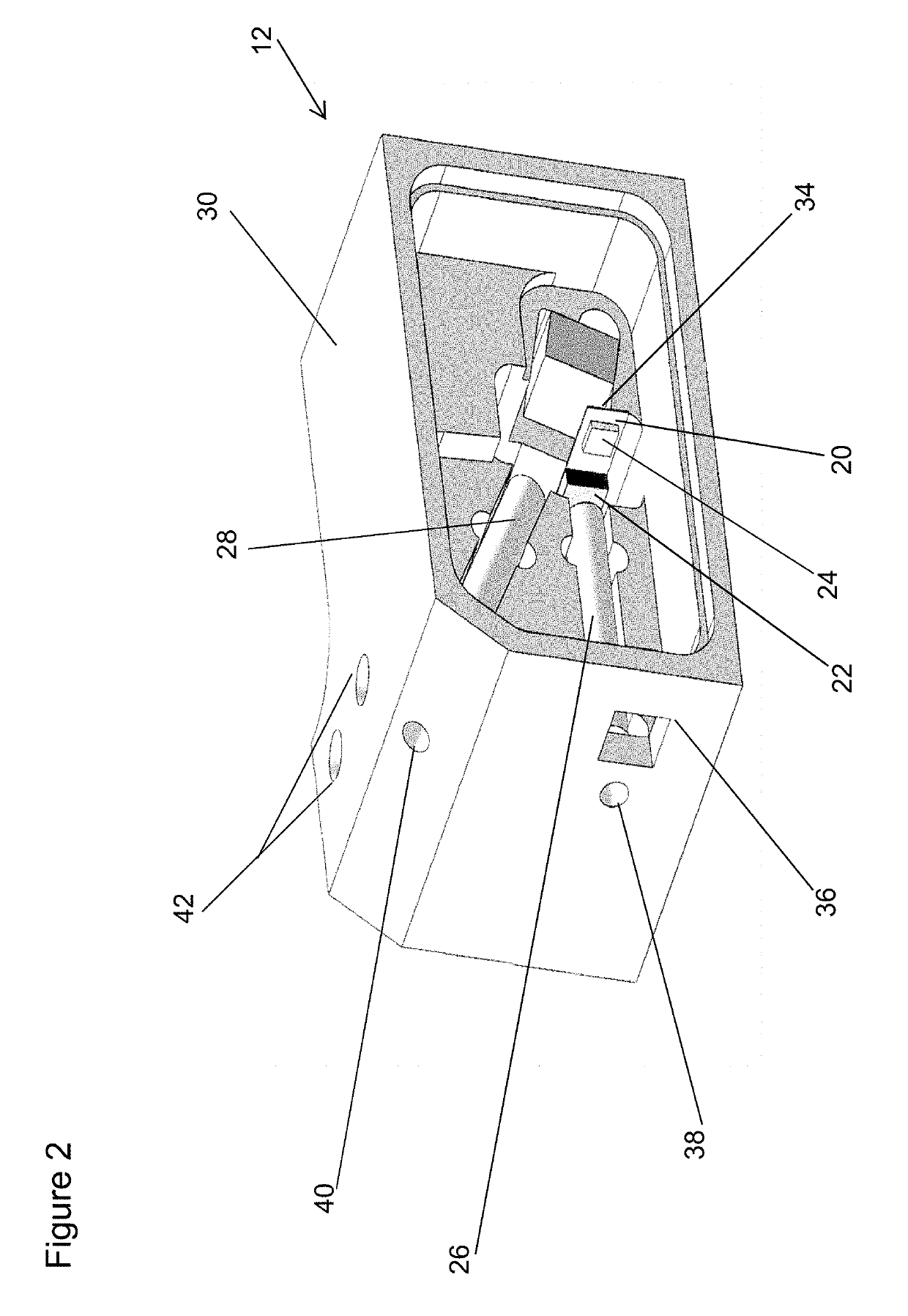
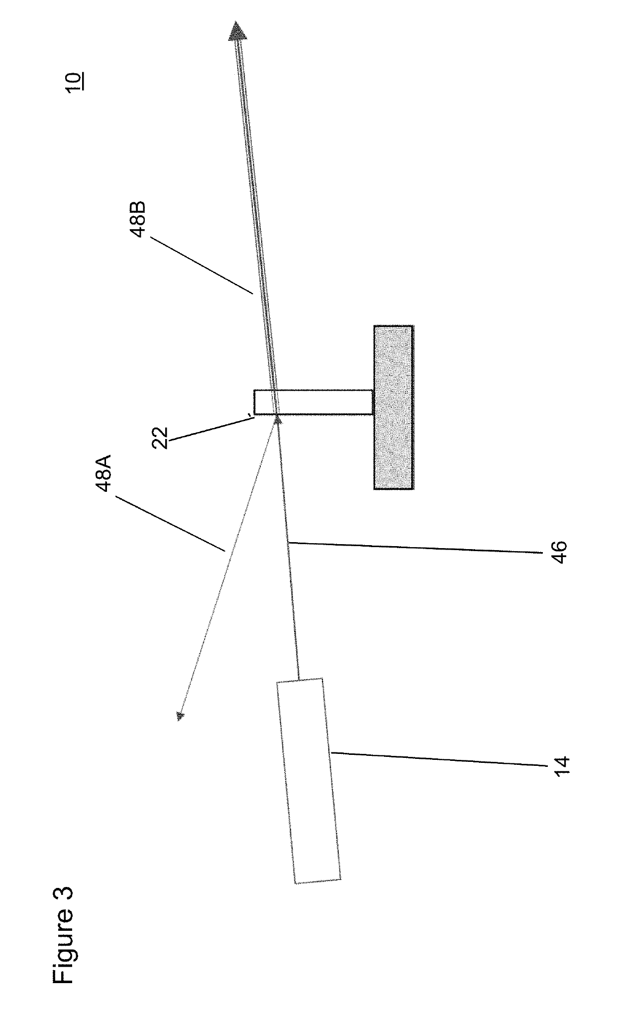
[0024]One aspect of the present technology relates to a photonic pressure sensor device. The photonic pressure sensor device includes a cantilever pivotally attached to a fixed mount. The cantilever has an electromagnetic reactive material located thereon. The electromagnetic reactive material is configured to cause a movement of the cantilever based on a photonic pressure exerted on the electromagnetic reactive material from an electromagnetic radiation source incident on the electromagnetic reactive material. An etalon is coupled to the cantilever such that a position of the etalon changes based on the movement of the cantilever. A light source is optically coupled to the etalon to provide a light beam to the etalon. The change in the position of the etalon causes interference of the light within the etalon resulting in an interference light beam. A light detector is positioned to r...


PUM

PropertyMeasurementUnit
thicknessaaaaaaaaaa
pressureaaaaaaaaaa
electromagnetic radiationaaaaaaaaaa

Abstract

A photonic pressure sensor device includes a cantilever pivotally attached to a fixed mount. The cantilever has an electromagnetic reactive material located thereon that is configured to cause a movement of the cantilever based on a photonic pressure exerted on the electromagnetic reactive material from an electromagnetic radiation source incident on the material. An etalon is coupled to the cantilever such that a position of the etalon changes based on the movement of the cantilever. A light source is optically coupled to the etalon to provide a light beam to the etalon. The change in the position of the etalon causes interference of the light within the etalon resulting in an interference light beam. A light detector is positioned to receive the interference light beam from the etalon and configured to measure an intensity value for the interference light beam.

Description

[0001]This application claims the benefit of U.S. Provisional Patent Application Ser. No. 62 / 502,947 filed May 8, 2017, which is hereby incorporated by reference in its entirety.FIELD OF THE INVENTION[0002]The present technology pertains to the field of optical sensors, and the application of optical sensors to measure power from high power electromagnetic sources, including lasers and X-Rays. More specifically, the present technology relates to photonic pressure sensor devices and methods of use thereof.BACKGROUND OF THE INVENTION[0003]Electromagnetic radiation is radiant energy released by certain electromagnetic processes, including radio waves, microwaves, infrared (IR) light, visible light, ultraviolet (UV) light, X-rays, and gamma rays. In classical physics, electromagnetic radiation consists of waves, which are oscillations of electric and magnetic fields. Such electromagnetic waves are characterized by wavelength or frequency, which determines position on the electromagnetic...

Claims


Application Information

Patent Timeline
Patent Type & Authority Patents(United States)
IPC IPC(8): G01J1/56G01N21/41G02B6/122G01T1/16G01N23/00G01L9/00G02B6/26G02B6/32
CPCG01N21/4133G01J1/56G01N23/00G02B6/1225G01L9/0076G01T1/16G02B6/262G02B6/32
Inventor PRADHAN, ATULSTELICK, SCOTT
Owner MICATU
Why Eureka
Try Eureka