Trigger controlled release of controlled numbers of projectiles at each of controlled number of instances per revolution in a centrifugal propulsion weapon

a centrifugal propulsion and projectile technology, applied in the field of automatic weapons, can solve the problems of limited projectile speed, inability to feed the desired amount of projectiles in any centrifugal operated weapon, and the power required to rotate the radial barrel too much to develop an economically feasible rapid fire weapon. , to achieve the effect of high speed

Inactive Publication Date: 2009-03-03
ST GEORGE CHARLES
View PDF5 Cites 7 Cited by
  • Summary
  • Abstract
  • Description
  • Claims
  • Application Information

AI Technical Summary

Benefits of technology

[0016]It is an object of the present invention, as it was of the Inventor's previous invention, to provide a novel automatic weapon utilizing centrifugal force which provides both a high rate of discharge (rounds per minute) and high muzzle velocity.
[0017]It likewise remains an object to provide such an automatic weapon which operates in a continuous stealth mode to increase its operational capabilities and the survivability of the weapon crew.
[0018]It likewise remains a further object to provide such a weapon which effectively eliminates overheating, jamming, the need for synchronized feeding and peripheral discharge, and any requirement for mechanical compensation for possible gyroscopic reaction.
[0020]It is a still further particular object of the present invention that any of the of (1) instances of the release of projectiles, (2) the numbers of projectiles released per instance, and (3) the numbers of instances per revolution at which projectiles may selectively be released, should be easily, positively, exactingly and reliably controllable.
[0043]Finally, a projectile release mechanism controls passage of projectiles within the at least one channel of the rotating member, and thus the escape of these projectiles from the periphery of the rotating member, and thus the ejection of these projectiles from the weapon. This projectile release mechanism is continuously so functional for controlling passage of the projectiles when the rotational speed and force of the prime mover is varied in a range between (1) essentially zero, where but few projectiles infrequently dribble from the weapon with essentially zero ejection velocity, and (2) a high rate of speed where multiplicities of more than 10 projectiles each minute are ejected from the weapon at speeds greater than 100 feet per second;

Problems solved by technology

A limitation of such a construction is that the power required to rotate the radial barrel is too great to develop an economically feasible rapid fire weapon.
Such construction has, however, limited the speed of the projectiles for various reasons including (1) rotation of the bullet in a direction reverse to travel direction of the projectile and (2) the provision of a peripheral barrier which prevents emission of the projectile at the precise moment that it achieves its maximum speed at the exit end of the barrel.
Associated with the foregoing type of gun has been the problem of overcoming the strong gyroscopic reaction force of a rotating impeller that resists turning and moving a gun when aiming in a plane that is not perpendicular to the axis of rotation of the impeller.
Such gravity feed loading systems are not able to feed the desired amount of projectiles in any centrifugal operated weapon at high speeds since the rotating member that provides the centrifugal force to propel the projectiles expels the projectiles much faster than any gravity feed loading system can supply.
Thus, the rate of fire of these weapons is restricted by having the rate of fire controlled by gravity fed loading systems.

Method used


Image

  • Trigger controlled release of controlled numbers of projectiles at each of controlled number of instances per revolution in a centrifugal propulsion weapon
  • Trigger controlled release of controlled numbers of projectiles at each of controlled number of instances per revolution in a centrifugal propulsion weapon
  • Trigger controlled release of controlled numbers of projectiles at each of controlled number of instances per revolution in a centrifugal propulsion weapon

Examples


Embodiment Construction

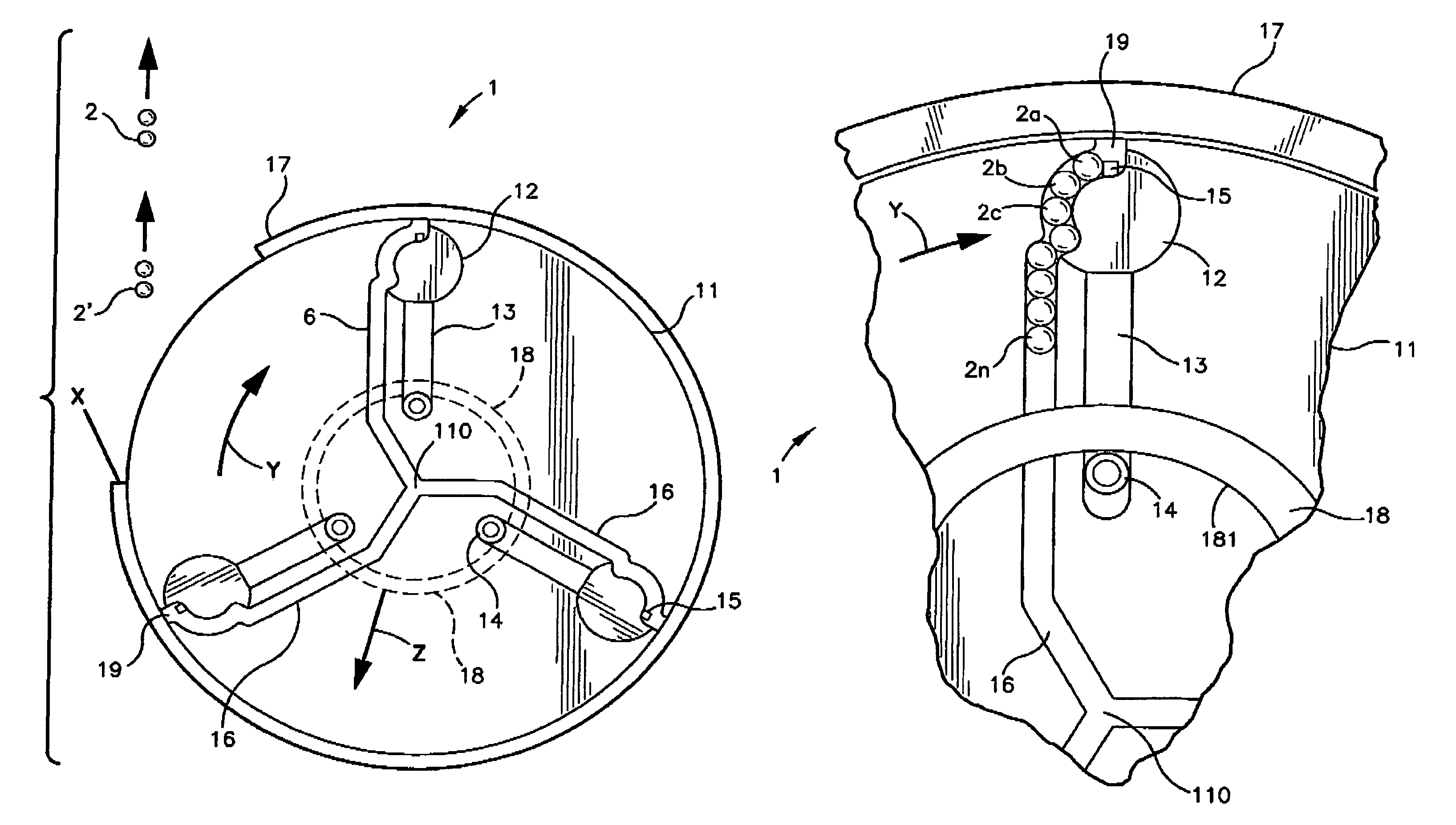
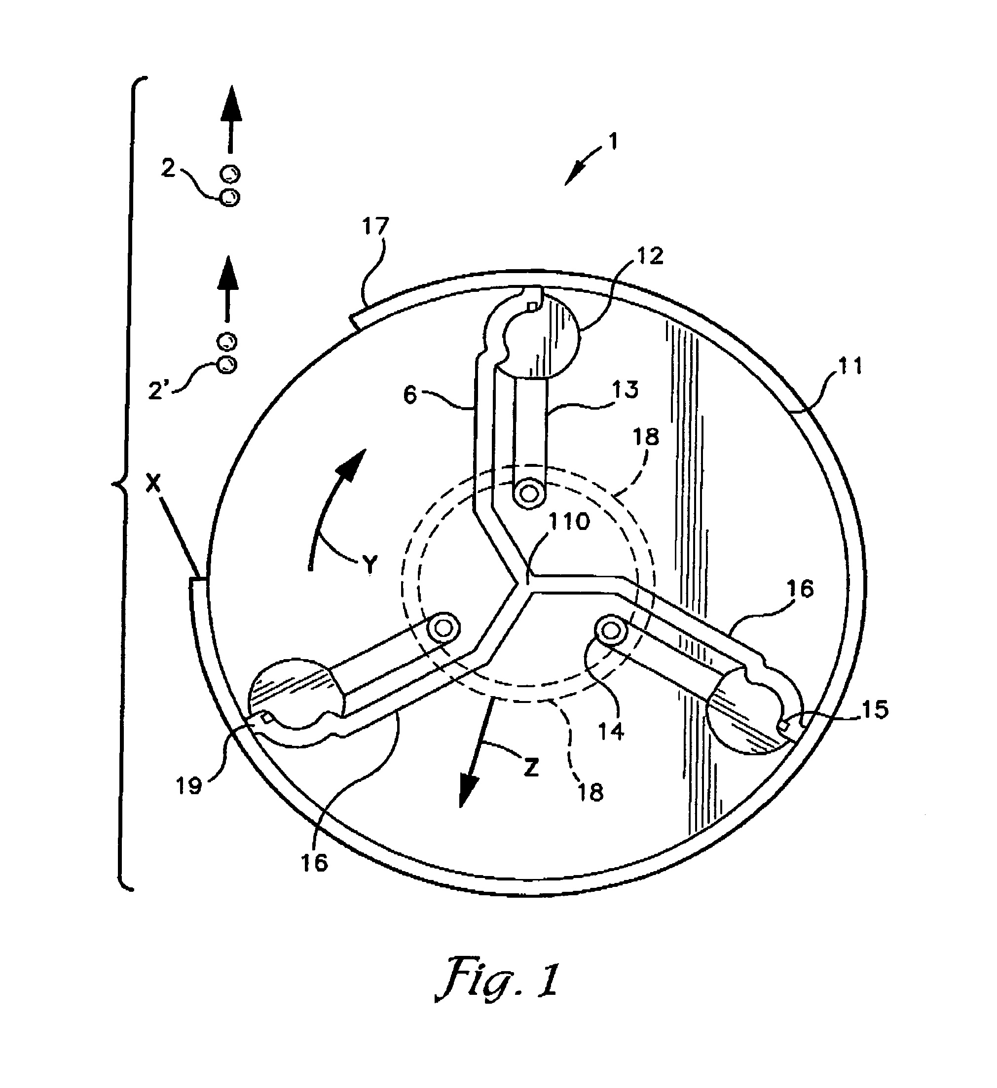
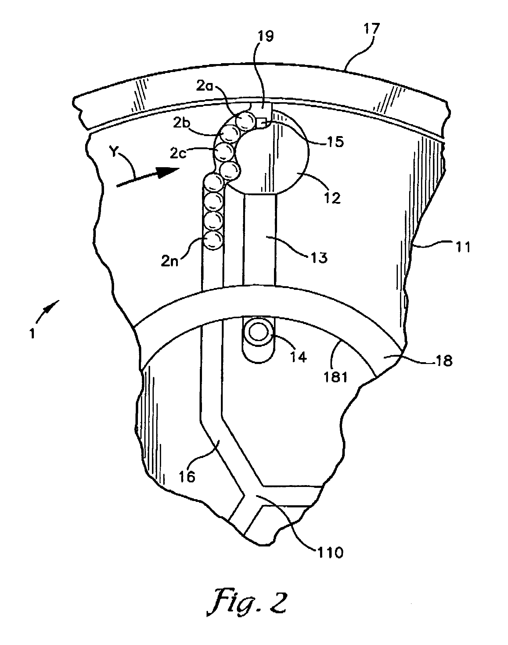
[0058]The following description is of the best mode presently contemplated for the carrying out of the invention. This description is made for the purpose of illustrating the general principles of the invention, and is not to be taken in a limiting sense. The scope of the invention is best determined by reference to the appended claims.

[0059]Although specific embodiments of the invention will now be described with reference to the drawings, it should be understood that such embodiments are by way of example only and are merely illustrative of but a small number of the many possible specific embodiments to which the principles of the invention may be applied. Various changes and modifications obvious to one skilled in the art to which the invention pertains are deemed to be within the spirit, scope and contemplation of the invention as further defined in the appended claims.

1. GENERAL OPERATION AND PRINCIPLES OF THE INVENTION

[0060]In accordance with the present invention an electrica...


PUM


Abstract

A weapon 1 peripherally discharging projectiles 2a-2n, normally ball bearings, at sustained high rates under centrifugal force has at least one member 11 rotating within a housing, or guide track, 10. Each rotating member 11 has at least one channel, or track, 16 with a radial component within which projectiles 2a-2n received near the center of rotation progress radially outwards until first escaping at 19, and then being ejected at X, under centrifugal force at the periphery of the at least one rotating member 11. A projectile release mechanism controls the timing, locations, and numbers of projectiles released per rotation of the at least one rotating member. This mechanism uses (1) an elongate member 13, substantially positioned along a radius line and within the at least one member 11 with its distal end protruding within the at least one channel 16 and with a proximal end cam follower 13 contacting the interior circumference 181 of (2) a ring cam 18, non-rotating to the housing 10 and movable between positions both coaxial, and displaced, to the rotational axis of the at least one rotating member 11. The elongate arm 13 moves (1) radially outward under centrifugal force of the rotation of the at least one rotating member 11 until its distal end protrudes within the at least one channel 16, therein obstructing passage of projectiles 2a-2n along the channel 16 and any ejection of these projectiles 2a-2n from the periphery of the at least one rotating member 11, until (2) the cam follower 14 of the elongate arm 13 contacts during rotation the cam 181 surface of the ring cam 18, pulling the elongate arm 13 against centrifugal force radially inwards until its distal end ceases to protrude within the channel 16, losing passage of projectiles 2a-2n along the channel 16 for subsequent escape at 19 and for ejection at X.

Description

REFERENCE TO A RELATED APPLICATION[0001]The present application claims benefit of priority of Australian Provisional Patent Application No. 2004906627, filed 19 Nov. 2004, to the selfsame inventor as is the present patent applicationBACKGROUND OF THE INVENTION[0002]1. Field of the Invention[0003]The present invention generally relates to automatic weapons using centrifugal force to propel projectiles.[0004]The present invention particularly relates to projectile trigger and release mechanisms for rotating weapons propelling projectiles by centrifugal force.[0005]The present invention still more particularly relates to control of each of (1) the release of projectiles, (2) the numbers of projectiles released, and (3) the numbers of instances per revolution at which projectiles may selectively be released, in a rotating weapon propelling projectiles by centrifugal force.[0006]2. Background of the Invention2.1 A SPECIFIC PRIOR PATENT[0007]The present invention is related to the invento...

Claims


Application Information

Patent Timeline
Patent Type & Authority Patents(United States)
IPC IPC(8): F41B3/04
CPCF41B3/04
Inventor ST. GEORGE, CHARLES
Owner ST GEORGE CHARLES
Why Eureka
Try Eureka