Manifold and filter assembly with filter basket

a filter basket and manifold technology, applied in the direction of filtration separation, machines/engines, separation processes, etc., can solve the problem that the manifold housing begins to fill with medical was

Active Publication Date: 2009-03-03
STRYKER CORP
View PDF51 Cites 79 Cited by
  • Summary
  • Abstract
  • Description
  • Claims
  • Application Information

AI Technical Summary

Benefits of technology

[0007]By providing this fluid bypass, the manifold and filter assembly of the present invention eliminates the backup of the medical waste to the inlet thereby allowing the medical waste to continually flow through the manifold and filter assembly even when the manifold and filter assembly is spent, i.e., the filter basket is filled.

Problems solved by technology

Currently, once the filters are plugged with debris, the manifold housing begins to fill with the medical waste.

Method used


Image

  • Manifold and filter assembly with filter basket
  • Manifold and filter assembly with filter basket
  • Manifold and filter assembly with filter basket

Examples


Embodiment Construction

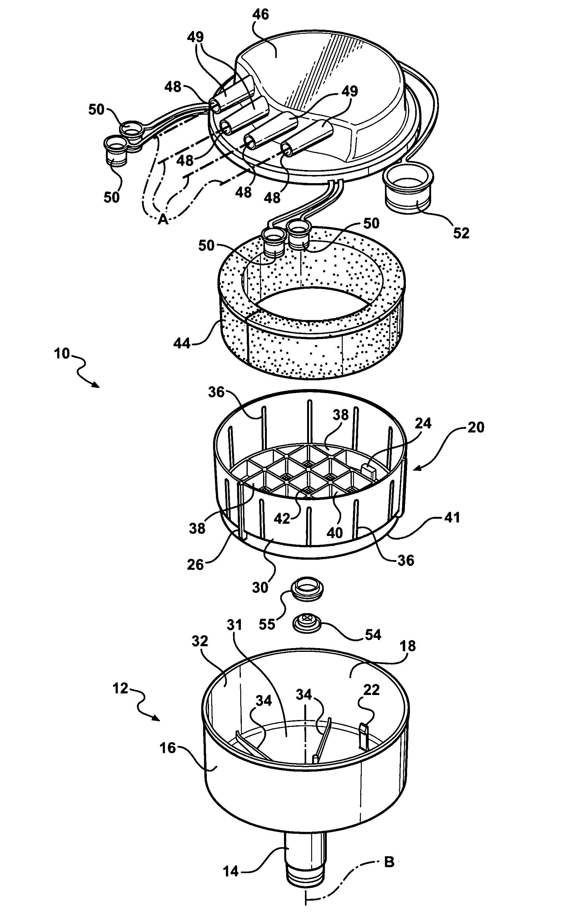
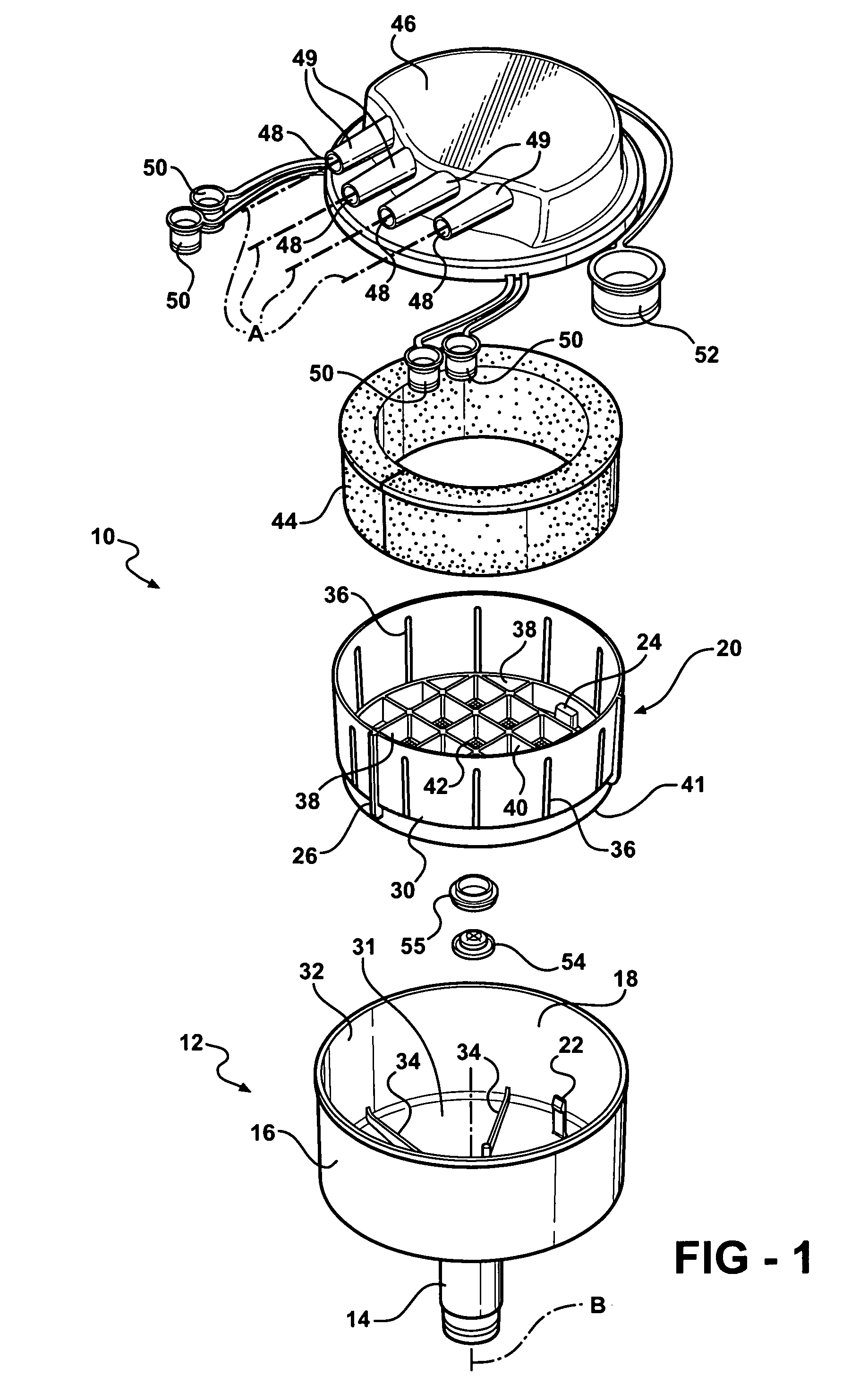
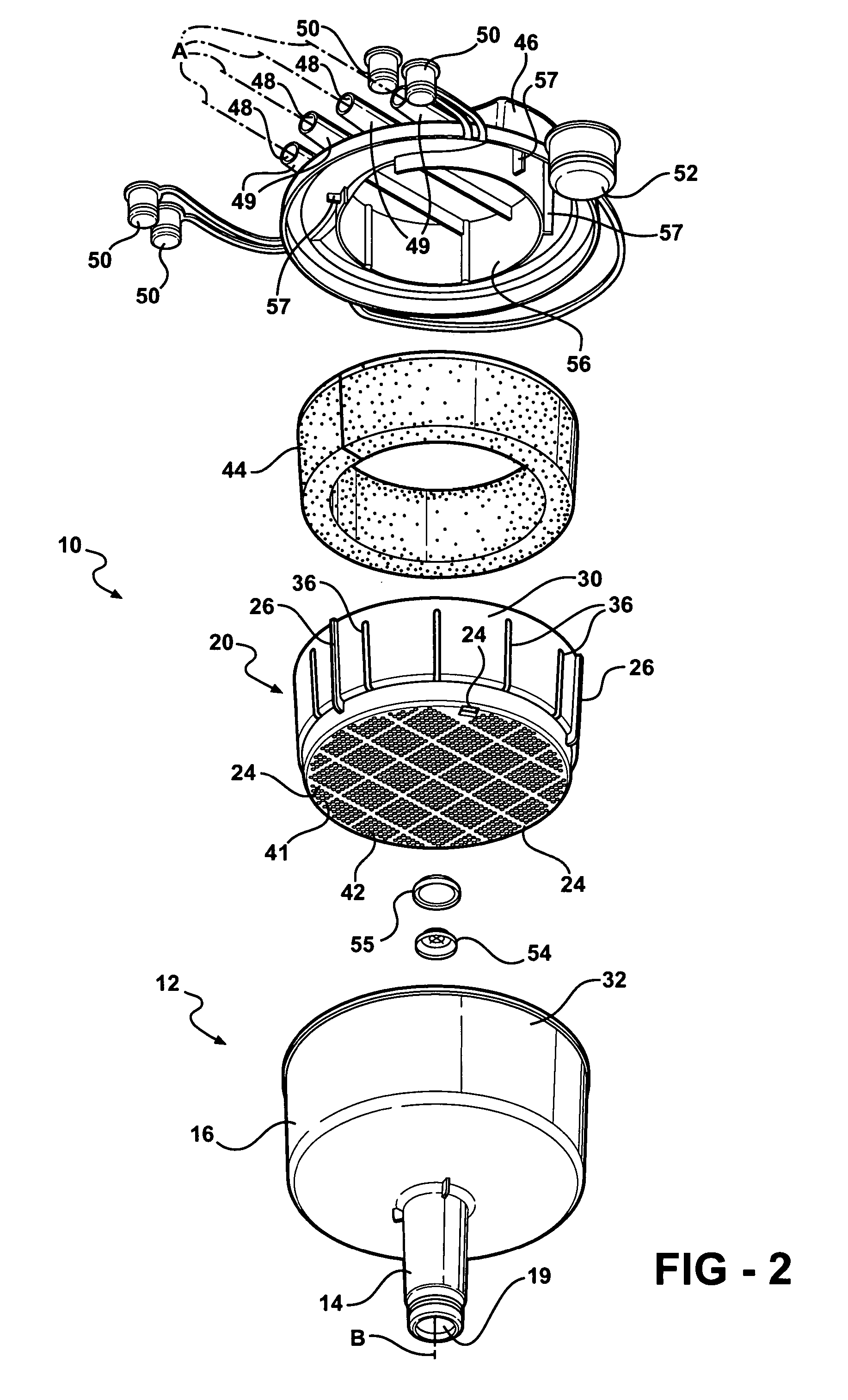
[0022]Referring to the Figures, wherein like numerals indicate like or corresponding parts throughout the several views, a manifold and filter assembly of the present invention is generally shown at 10. The assembly 10 is intended for use with waste collection units to collect medical waste such as bodily fluids and materials from patients during medical procedures. Examples of waste collection units can be found in U.S. Pat. Nos. 5,997,733; 6,180,000; and 6,222,283, all incorporated herein by reference. Another example of a waste collection unit is shown at 15 in FIG. 18.

[0023]Referring to FIGS. 1 and 2, the assembly 10 has a base 12. The base 12 includes a cup-shaped manifold body 16 and a neck 14 (outlet tube 14) extending downwardly from the manifold body 16 to define an outlet 19. The neck 14 is adapted to be inserted into an inlet of a waste collection unit, such as the inlet 17 of the waste collection unit 15 shown in FIG. 18. The manifold body 16 defines a chamber 18. The ch...


PUM

PropertyMeasurementUnit
distanceaaaaaaaaaa
pressureaaaaaaaaaa
semi-transparentaaaaaaaaaa

Abstract

A manifold and filter assembly for use with a waste collection unit is provided. The manifold and filter assembly directs and filters medical waste flowing into the waste collection unit. The manifold and filter assembly comprises a manifold body defining a chamber and an outlet for directing the medical waste into the waste collection unit. A manifold cap is fitted to the manifold body to close the chamber. The manifold cap defines a plurality of inlets for receiving the medical waste. A filter basket having a bottom and a peripheral wall defining a plurality of openings is snap-locked to the manifold body. The filter basket is positioned such that a fluid bypass is formed between the filter basket and the manifold body and between the filter basket and the manifold cap. The fluid bypass is in fluid communication with the outlet whereby the medical waste can flow over the peripheral wall to the outlet through the fluid bypass.

Description

RELATED APPLICATIONS[0001]This application claims the benefit of U.S. provisional patent application Ser. No. 60 / 545,974, filed Feb. 19, 2004, the advantages and disclosure of which are herein incorporated by reference.FIELD OF THE INVENTION[0002]The present invention relates generally to a manifold and filter assembly and more particularly to a manifold and filter assembly for use with a waste collection unit to direct and filter medical waste, e.g., bodily fluids and materials, entering the waste collection unit.BACKGROUND OF THE INVENTION[0003]Waste collection units are well known for use in surgical environments to collect medical waste such as bodily fluids and materials during a surgical procedure. Examples of waste collection units can be found in U.S. Pat. Nos. 5,997,733; 6,180,000; and 6,222,283. For instance, U.S. Pat. No. 5,997,733 discloses a waste liquid and smoke disposal system which combines the functions of a smoke extraction system and a waste collection unit, typi...

Claims


Application Information

Patent Timeline
Patent Type & Authority Patents(United States)
IPC IPC(8): B01D35/28B01D29/11B01D35/00A61L11/00A61M1/00B01D24/00B01D29/03B01D29/52B01D35/34B09B3/00
CPCA61M1/0056B01D29/03B09B3/0075B01D29/50A61M2209/084B01D2201/204B01D2201/48A61M1/79A61M1/88
Inventor HERSHBERGER, DAVIDHUYSER, RICHARD F.ISHAM, STEPHEN P.MACDONALD, BRUCENOONAN, MICHAELSTALEY, KAREN
Owner STRYKER CORP
Why Eureka
Try Eureka