
Multi-textured reflective display

Inactive Publication Date: 2009-03-03
SERIGRAPH INC
View PDF24 Cites 8 Cited by
  • Summary
  • Abstract
  • Description
  • Claims
  • Application Information

AI Technical Summary

Benefits of technology

[0004]Highly reflective materials have long been known to attract the human eye. Metallic inks, hot stamping foils, vacuum metallized substrates, metallic flakes incorporated into inks and coatings have all been used to impart such eye catching and aesthetically pleasing effects to decorated articles. Each of these techniques has advantages and disadvantages. The major disadvantage has been the inability to apply a metallic or holographic effect selectively and impart texture and / or thickness if desired to the metallic area. The ability to selectively apply metallics has been limited to printing metallic inks, selectively blocking out a metallic substrate (only allowing the desired areas of the metallic substrate to show through), or to hot stamp. Metallic inks do not have the reflective brilliance of vacuum metallized foils and substrates. Hot stamping requires the use of expensive equipment and expensive hot stamping dyes. The above noted incorporated U.S. Pat. No. 6,170,881 provides one solution. The parent invention provides a further improvement, including enhanced economy of manufacture.

Problems solved by technology

The major disadvantage has been the inability to apply a metallic or holographic effect selectively and impart texture and / or thickness if desired to the metallic area.
The ability to selectively apply metallics has been limited to printing metallic inks, selectively blocking out a metallic substrate (only allowing the desired areas of the metallic substrate to show through), or to hot stamp.
Metallic inks do not have the reflective brilliance of vacuum metallized foils and substrates.
Hot stamping requires the use of expensive equipment and expensive hot stamping dyes.

Method used


Image

  • Multi-textured reflective display
  • Multi-textured reflective display
  • Multi-textured reflective display

Examples


Embodiment Construction

Parent Application

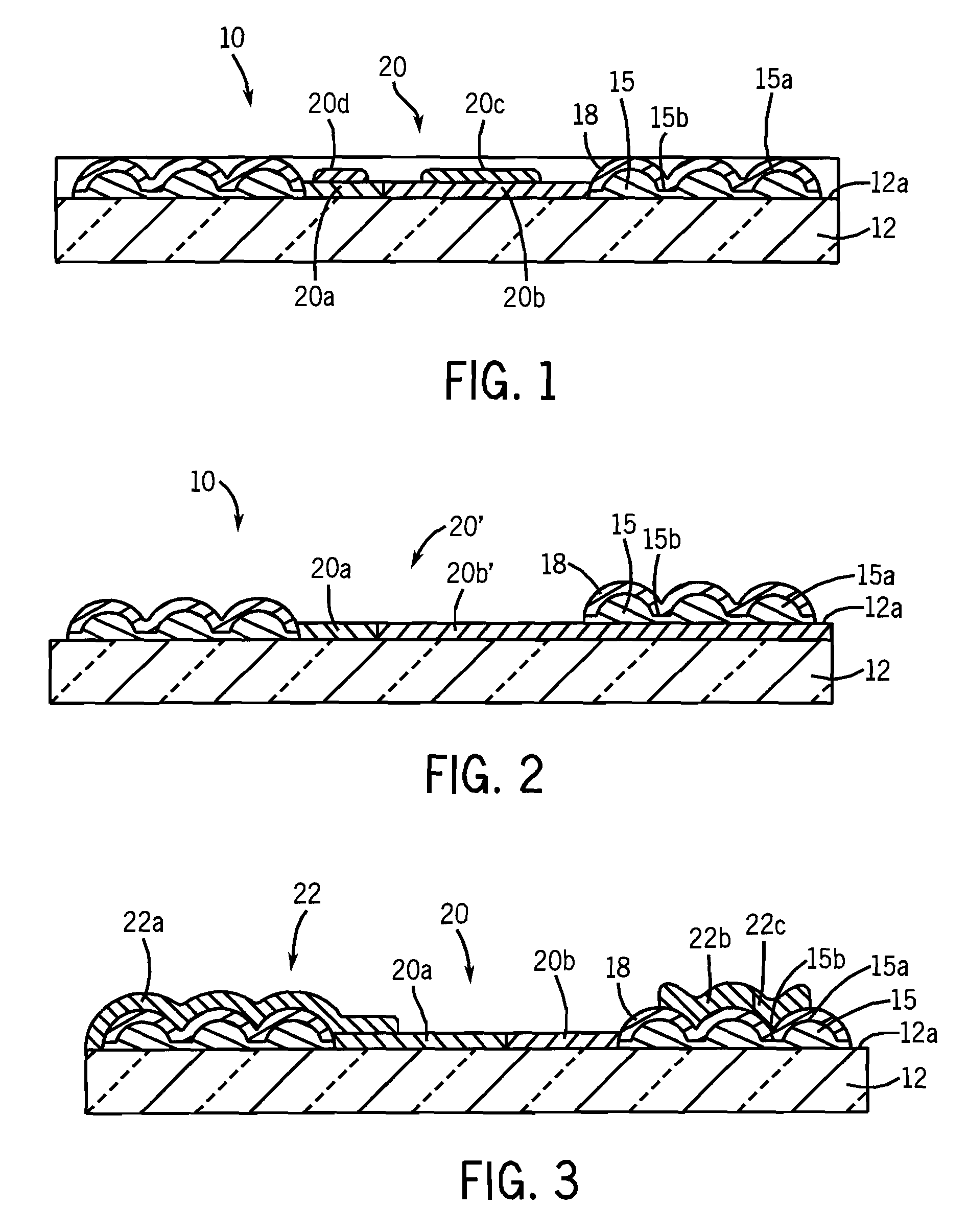
[0017]As illustrated in FIG. 1, a display is provided by printed article 10 having a visual display formed thereon which is manufactured in accordance with a method of the parent invention. The article 10 includes a base sheet 12 which can be opaque or transparent, and flexible or rigid.

[0018]An opaque sheet 12 can be formed of paper, cardboard, metal, or any other suitable material. An opaque sheet is appropriate for producing trading cards, greeting cards, signs, posters, labels, book covers, decorative panels, name plates, and the like. Alternatively, the sheet 12 can be replaced by an object having a flat surface, such as the side of a building.

[0019]A transparent sheet 12 can be formed of plastic, glass, or any other suitable material. A transparent sheet is appropriate for producing details and the like, and can also be used for producing other items with a rear surface reflective layer and protective cover, in addition to a front surface reflective layer and...


PUM


Abstract

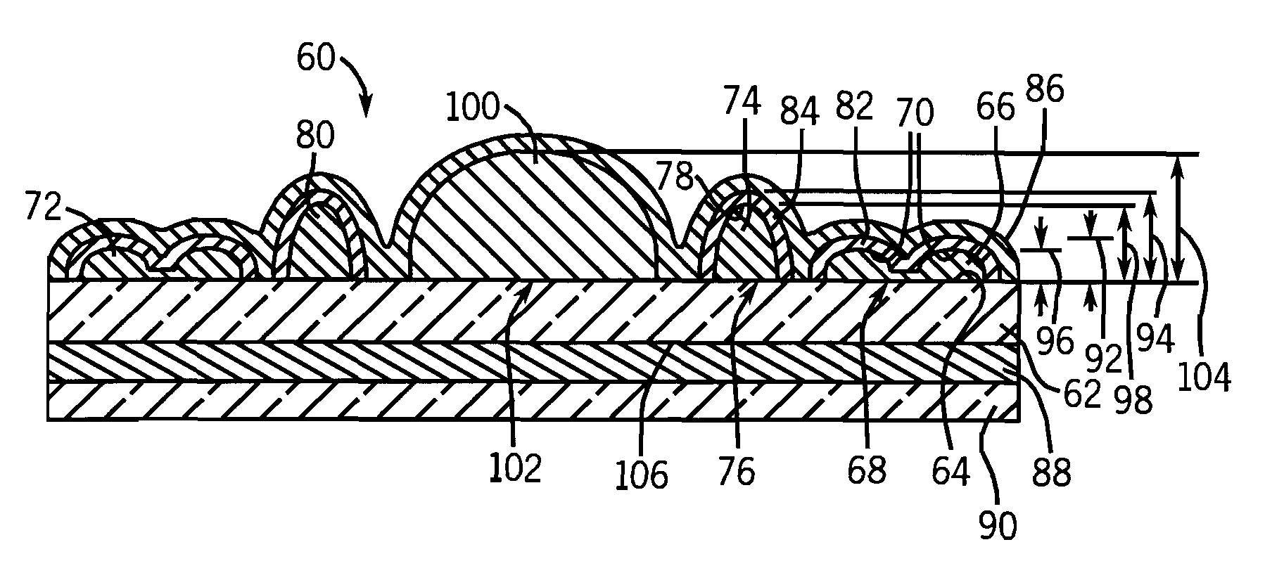
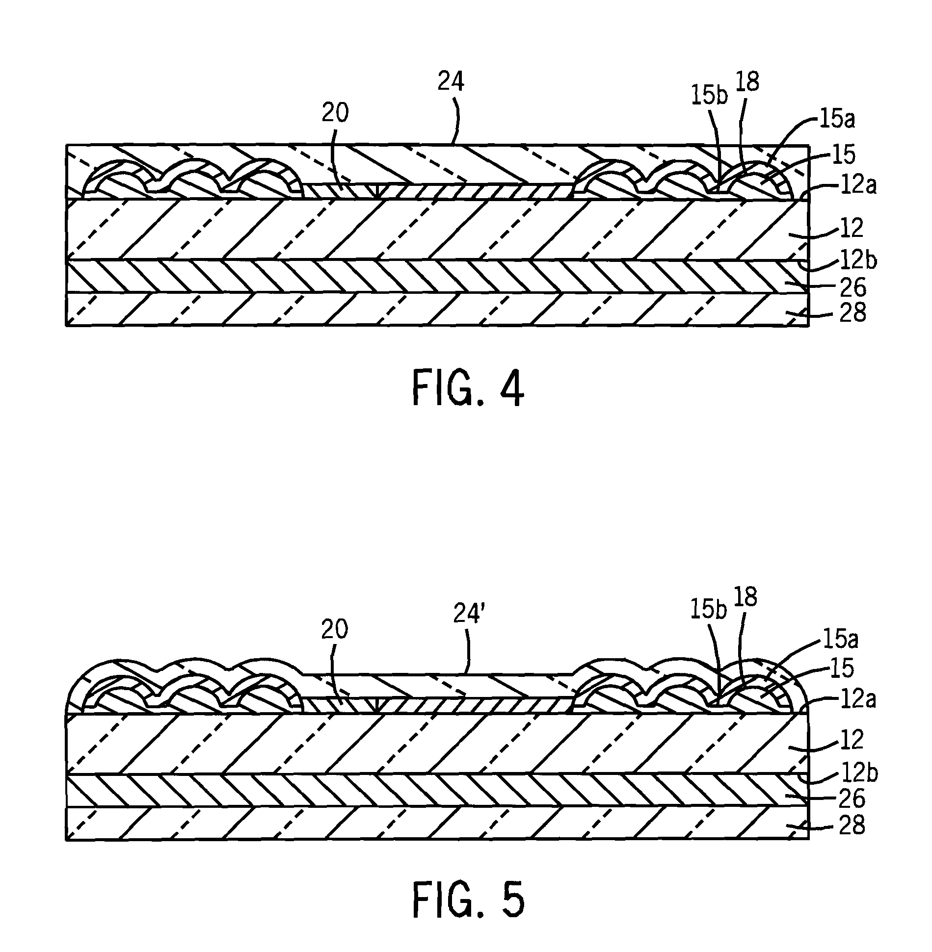
A printed substrate includes multi-textured patterns and reflective layers thereover. An economical manufacturing method is provided. A printed circuit board is further provided.

Description

CROSS-REFERENCE TO RELATED APPLICATION[0001]This application is a Continuation-In-Part of U.S. patent application Ser. No. 10 / 388,782, filed Mar. 14, 2003 now U.S. Pat. No. 7,048,307.BACKGROUND AND SUMMARY[0002]The invention of the noted parent application relates to reflective displays, including image displays, and methods of manufacture, for example trading cards, greeting cards, signs, posters, labels, decals, book covers, decorative panels, packaging, name plates, and other displays including designs incorporating a selective area of metallic appearance resembling liquid metal, and other reflective displays.[0003]The parent invention arose during continuing development efforts relating to image displays, including printed articles, including subject matter related to U.S. Pat. Nos. 6,170,881 and 5,762,379 owned by the assignee of the present invention, and incorporated herein by reference.[0004]Highly reflective materials have long been known to attract the human eye. Metallic ...

Claims


Application Information

Patent Timeline
IPC IPC(8): B42D15/00
CPCB42D15/02B44C1/14B44F7/00G09F3/10G09F13/16H05K3/046H05K2203/0522H05K2203/0528
Inventor REINDL, MICHAEL G.TERLIZZI, MICHAEL A.SCARBROUGH, JOEL SCOTT
Owner SERIGRAPH INC
Learn More