Premixing burner and method for operating a premixing burner

Inactive Publication Date: 2010-07-22
SIEMENS AG
View PDF11 Cites 17 Cited by
  • Summary
  • Abstract
  • Description
  • Claims
  • Application Information

AI Technical Summary

Benefits of technology

[0014]In respect of nitrous oxide minimization the addition of inert mass flows as a thinning medium into the air mass flow or the fuel mass flow (quenching) is usual. The use of the leaner premix technology makes it possible to reduce the quantity of the quenching medium employed, which enhances the economy of the plant. Howeve

Problems solved by technology

However the lack of inerting then me

Method used


Image

  • Premixing burner and method for operating a premixing burner
  • Premixing burner and method for operating a premixing burner
  • Premixing burner and method for operating a premixing burner

Examples


Embodiment Construction

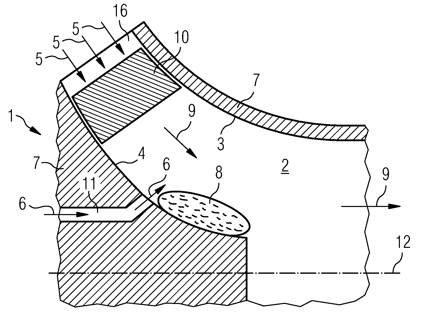
[0034]The invention will be explained below in greater detail with reference to FIGS. 1 to 5. FIG. 1 shows a schematic diagram of a section through a part of a conventional premixing burner 1. The premixing burner 1 includes elements such as a housing 7, a premixing zone 2, a swirl generator 10 and / or one or more fuel nozzles 11. The premixing zone is arranged radial-symmetrically around the central axis 12. The outer side of the premixing zone 2, viewed from the central axis 12, is referred to below as the cone side 3. The side of the premixing zone 2 facing towards a central axis 12 will be referred to below as the hub side 4.

[0035]An air mass flow 5 arrives at the swirl generator 10 via an air supply inlet 16. The air swirl generator 10 swirls the air mass flow 5 and directs this into the premixing zone 2. From there the air mass flow is forwarded in the main direction of flow 9 to the combustion chamber (not shown).

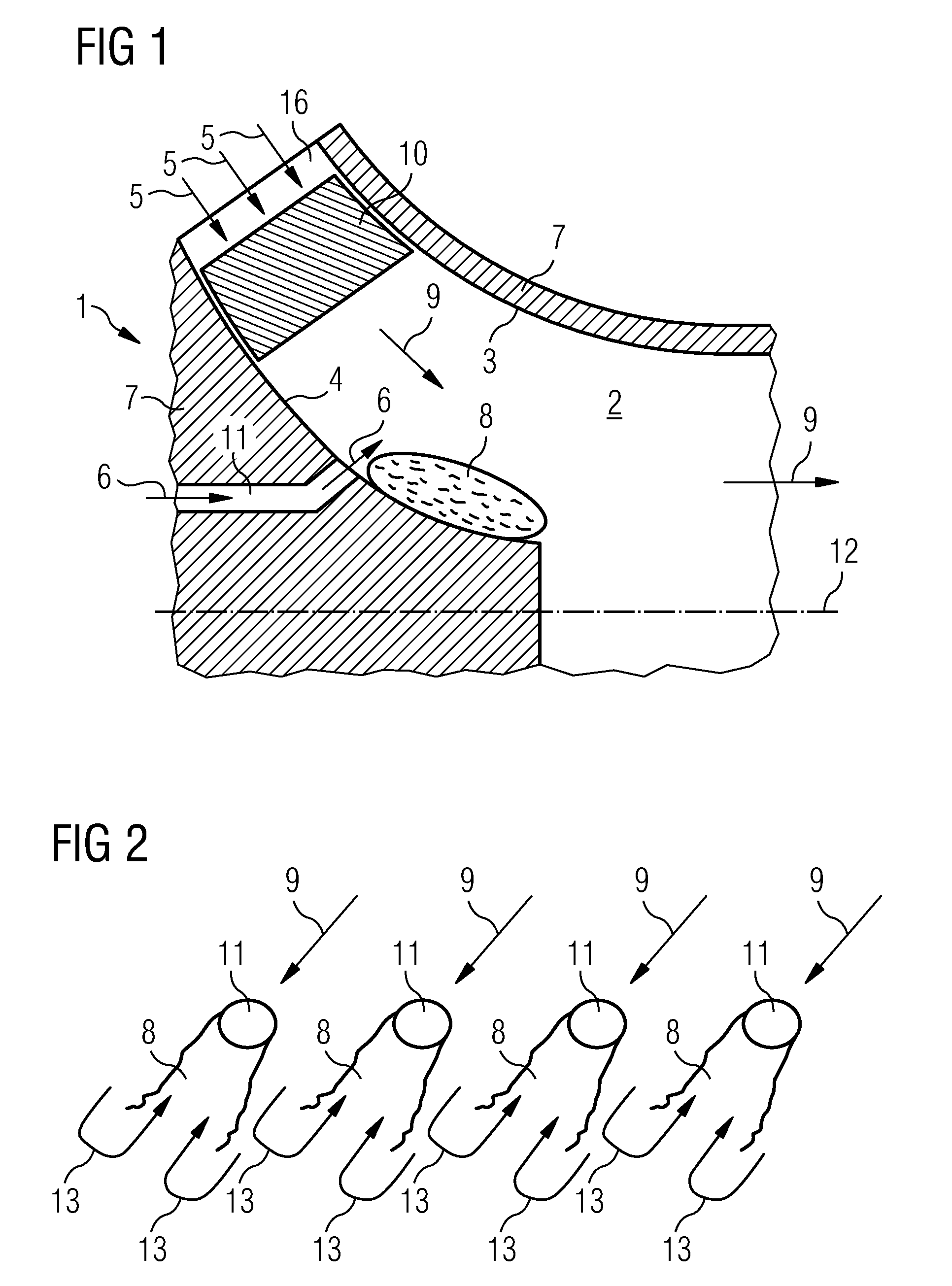
[0036]On the hub side 4 of the premixing zone 2 are located one ...


PUM


Abstract

A method for operating a premixing burner is provided. The premixing burner includes a premixing zone. An air mass flow and fuel may be injected into the premixing zone, and a potential hot gas backflow area may form. A fluid containing no fuel is injected downstream from the fuel injection into the premixing zone in order that a hot gas backflow area does not form. A premixing burner including a premixing zone is also provided.

Description

CROSS REFERENCE TO RELATED APPLICATIONS[0001]This application is the US National Stage of International Application No. PCT / EP2008 / 059658, filed Jul. 23, 2008 and claims the benefit thereof. The International Application claims the benefits of European Patent Office application No. 07014820.0 EP filed Jul. 27, 2007. All of the applications are incorporated by reference herein in their entirety.FIELD OF INVENTION[0002]The present invention relates to a premixing burner, especially a syngas premixing burner, and to a method for operating a premixing burner.BACKGROUND OF INVENTION[0003]Premixing burners typically comprise a premixing zone in which air and fuel are mixed before the mixture is directed into a combustion chamber. The mixture burns in said chamber, with a hot gas under increased pressure being generated. The hot gas is transferred on to the turbine. The primary consideration when operating premixing burners is to keep nitrous oxide emissions low and to avoid a flame blowba...

Claims


Application Information

Patent Timeline
IPC IPC(8): F23D14/24F23C7/00F23C5/08F23L7/00
CPCF23C7/004F23C2900/07001F23D11/383F23D2900/14021F23R3/286F23L2900/07002F23L2900/07009F23R3/14F23L7/00
Inventor KOSTLIN, BERTHOLDLENZE, MARTINPRADE, BERND
Owner SIEMENS AG
Why Eureka
Try Eureka