
System and method to control fuel injector reactivation during deceleration fuel shut off

a technology of fuel shut off and cylinder, which is applied in the direction of electrical control, machines/engines, output power, etc., can solve the problems of poor drivability, poor drivability, and potential, and achieve enhanced torque response, improved noise, vibration and harness

Active Publication Date: 2009-03-03
FORD GLOBAL TECH LLC
View PDF7 Cites 9 Cited by
  • Summary
  • Abstract
  • Description
  • Claims
  • Application Information

AI Technical Summary

Benefits of technology

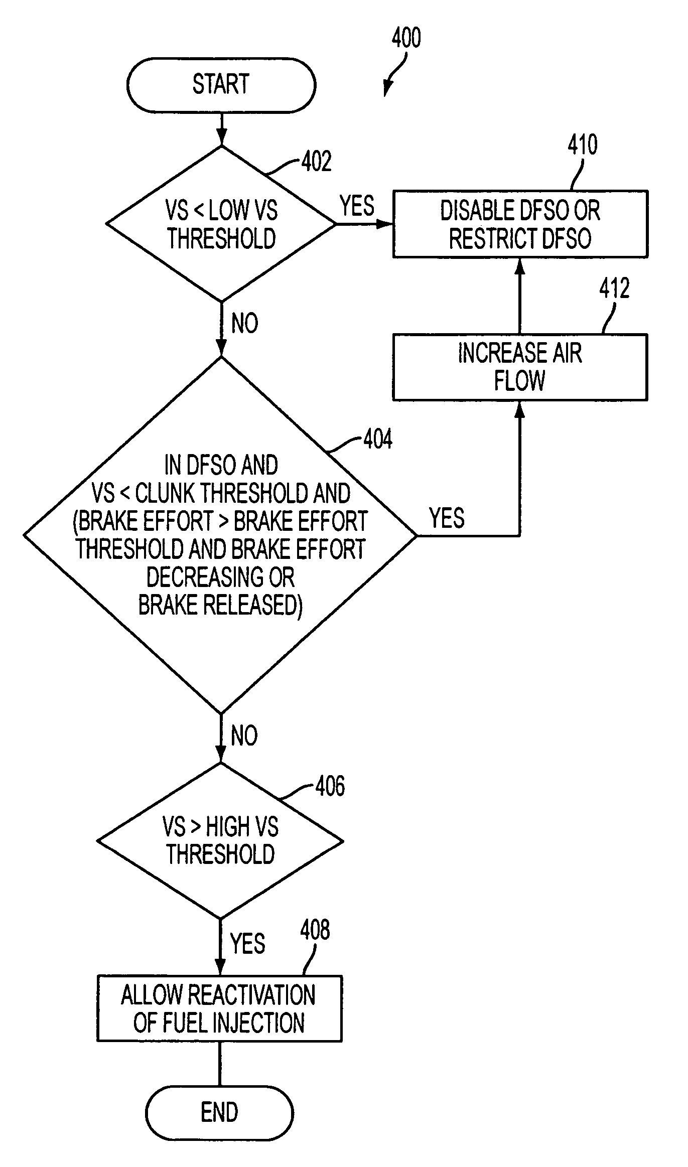
The patent text describes a system and method for controlling fuel injection in an internal combustion engine to improve fuel economy during deceleration fuel shut off (DFSO). The technical effect of the patent is to improve the torque response and driving experience during DFSO by reactivating fuel injectors based on the release or decrease of driver braking during deceleration fuel shut off. This allows time for the fuel injection and transmission control to stabilize torque control prior to a tip-in, improving the vehicle's feel and reducing the potential for engine misfire. Additionally, increasing air flow to cylinders before reactivating fuel injectors can reduce clunk and improve the driver's feel.

Problems solved by technology

However, the inventors herein have recognized that poor drivability may become an issue during deceleration fuel shut off (DFSO).
For example, a potential exists for poor drivability when the vehicle operator releases and subsequently engages the accelerator pedal.
Specifically, as described in U.S. Pat. No. 6,266,597, poor drivability may result due to transmission or driveline gear lash.
Thus, when exiting DFSO (e.g., re-enabling injectors), a driver may feel clunk if the injectors, combustion, transmission control and engine torque control do not have adequate time to stabilize.
Alternatively, if additional time is taken to re-enable engine operation to reduce clunk, the driver may experience a delayed vehicle response, thus potentially causing the vehicle to feel sluggish.

Method used


Image

  • System and method to control fuel injector reactivation during deceleration fuel shut off
  • System and method to control fuel injector reactivation during deceleration fuel shut off
  • System and method to control fuel injector reactivation during deceleration fuel shut off

Examples


Embodiment Construction

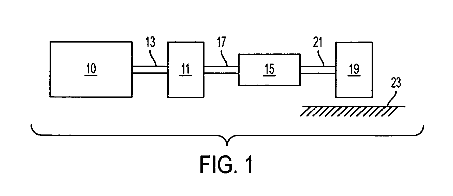
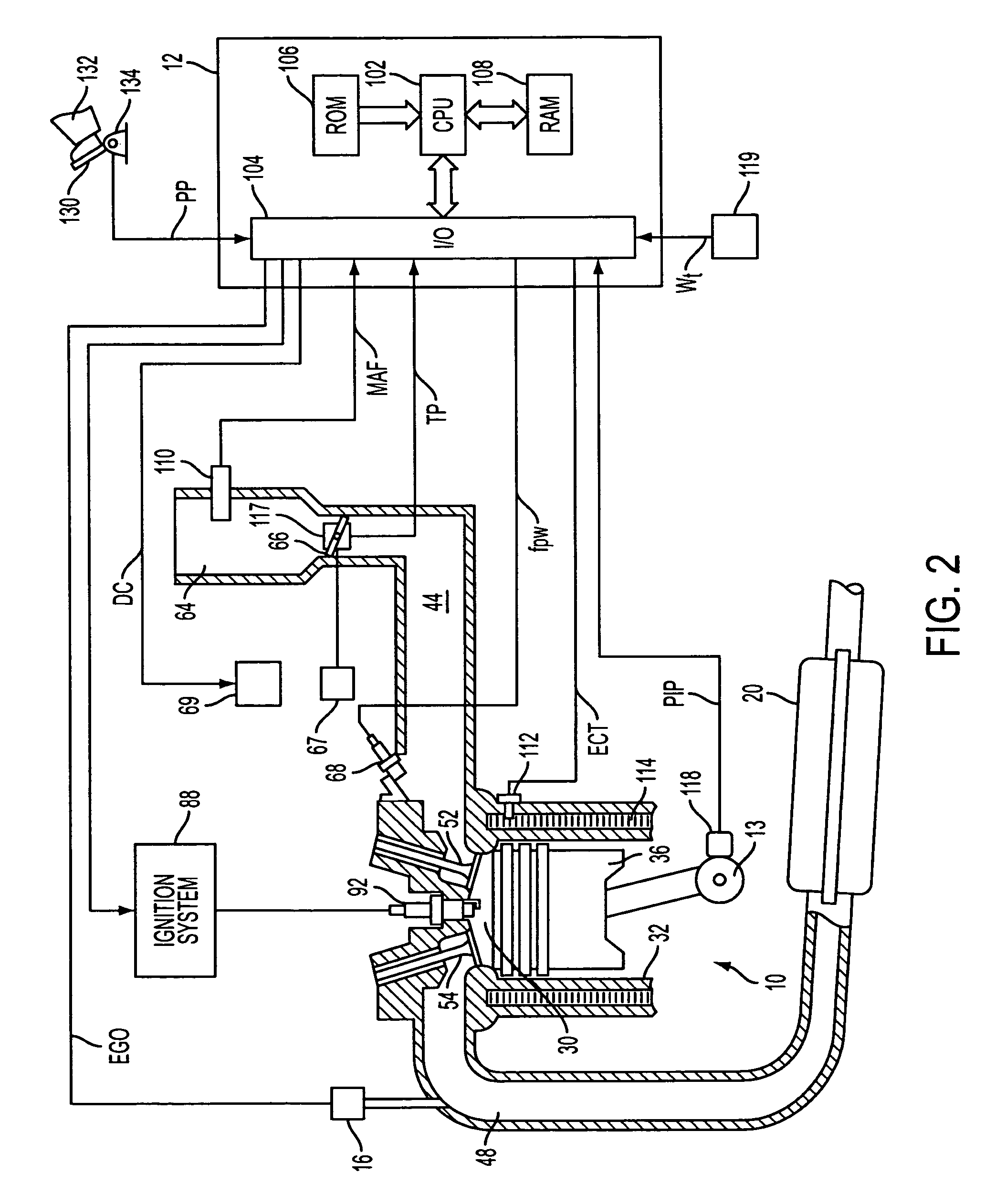
[0016]Referring to FIG. 1, internal combustion engine 10, further described herein with particular reference to FIG. 2, is shown coupled to torque converter 11 via crankshaft 13. Torque converter 11 is also coupled to transmission 15 via turbine shaft 17. Torque converter 11 has a bypass clutch (not shown) which can be engaged, disengaged, or partially engaged. When the clutch is either disengaged or partially engaged, the torque converter is said to be in an unlocked state. Turbine shaft 17 is also known as transmission input shaft. Transmission 15 comprises an electronically controlled transmission with a plurality of selectable discrete gear ratios. Transmission 15 also comprises various other gears, such as, for example, a final drive ratio (not shown). Transmission 15 is also coupled to tire 19 via axle 21. Tire 19 interfaces the vehicle (not shown) to the road 23. Note that in one example embodiment, this powertrain is coupled in a passenger vehicle that travels on the road.

[0...


PUM


Abstract

A method of controlling fuel injection in an engine of a vehicle comprises reactivating fuel injectors based on release or decrease of driver braking during deceleration fuel shut off operation. According to another aspect, a method of controlling fuel injection in an engine of a vehicle comprises reactivating fuel injectors based on release or decrease of driver braking during deceleration fuel shut off; and increasing air flow to a cylinder before reactivation of fuel injectors in response to said release or decrease of driver braking to enhance torque response. The methods allow an engine to exit DFSO earlier by making use the brake input and effort, which provides time to reactivate the fuel injection and stabilize torque control prior to tip-in.

Description

FIELD[0001]The present application relates generally to a system and method to control cylinder reactivation during deceleration fuel shut off, and more specifically to a system and method that improve the torque response and the drivability with deceleration fuel shut off operation.BACKGROUND AND SUMMARY[0002]In vehicles having internal combustion engines, it can be beneficial to discontinue Fuel injection to all or some of the engine cylinders during certain operating conditions, such as during vehicle deceleration or braking. The greater the number of cylinders deactivated, or the longer cylinders are deactivated, the greater the fuel economy improvement that can be achieved.[0003]However, the inventors herein have recognized that poor drivability may become an issue during deceleration fuel shut off (DFSO). For example, a potential exists for poor drivability when the vehicle operator releases and subsequently engages the accelerator pedal. Specifically, as described in U.S. Pat...

Claims


Application Information

Patent Timeline
Patent Type & Authority Patents(United States)
IPC IPC(8): B60W10/06B60W10/18
CPCF02D17/02F02D41/027F02D41/126F01N2430/06F02D41/0002F02D2200/0814Y10T477/877F02M69/044Y10T477/80Y10T477/814Y10T477/817Y10T477/87F02D2200/602
Inventor SEAMAN, JEFFBIDNER, DAVIDBEHR, KENLINENBERG, MARK
Owner FORD GLOBAL TECH LLC
Learn More