Flat shaft of a hip-joint prosthesis for anchoring in the femur

a hip joint and prosthesis technology, applied in the field of hip joint prosthesis for femur anchoring, can solve problems such as the risk of fracture of the bone, and achieve the effect of better anchoring

Inactive Publication Date: 2009-03-03
SMITH & NEPHEW ORTHOPAEDICS
View PDF31 Cites 40 Cited by
  • Summary
  • Abstract
  • Description
  • Claims
  • Application Information

AI Technical Summary

Benefits of technology

[0006]It is the objective of the present invention to disclose an improved shaft of

Problems solved by technology

This kind of compression is substantially less critical that that produced by known arrangements with proxima

Method used


Image

  • Flat shaft of a hip-joint prosthesis for anchoring in the femur
  • Flat shaft of a hip-joint prosthesis for anchoring in the femur
  • Flat shaft of a hip-joint prosthesis for anchoring in the femur

Examples


Embodiment Construction

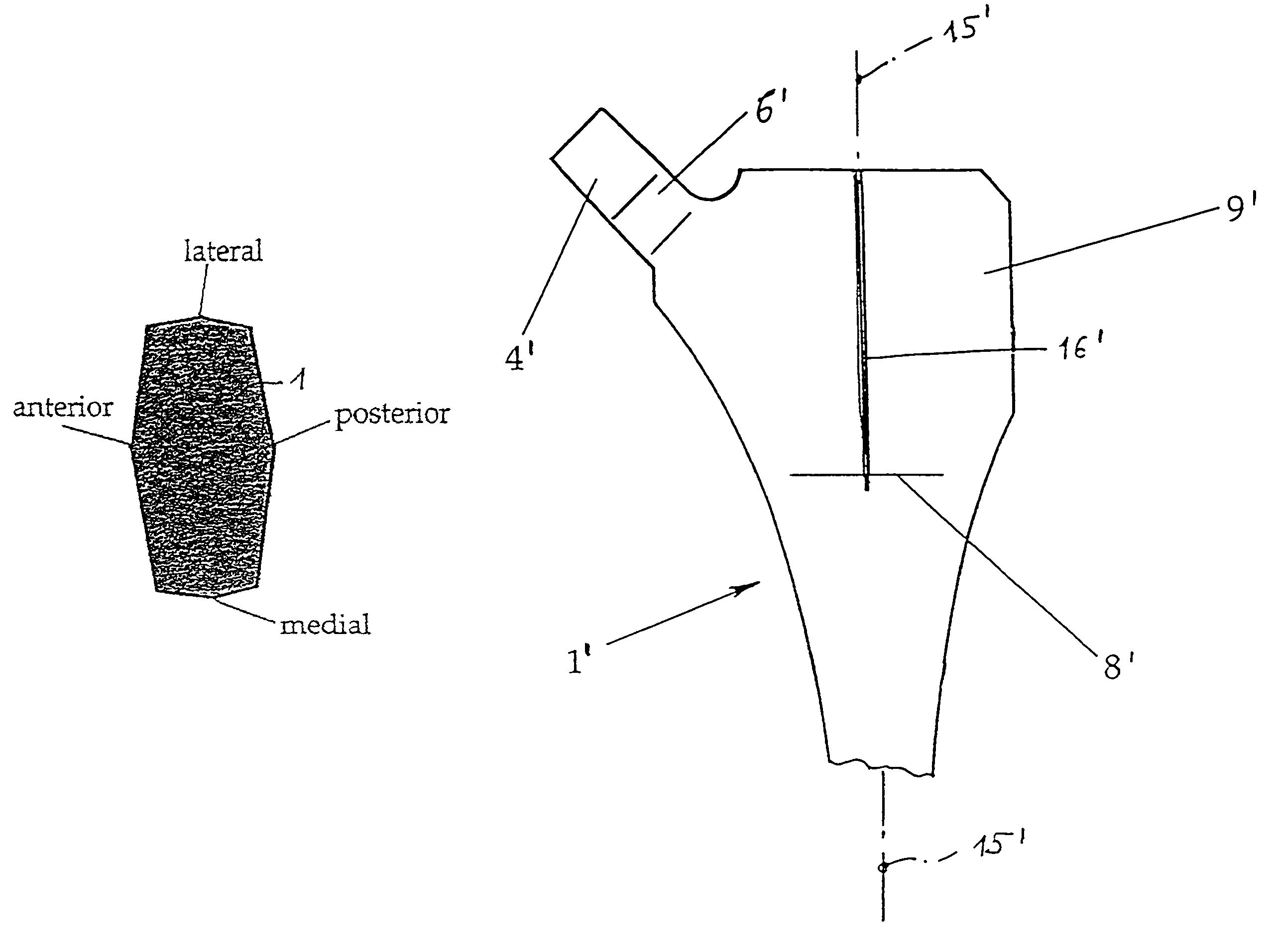
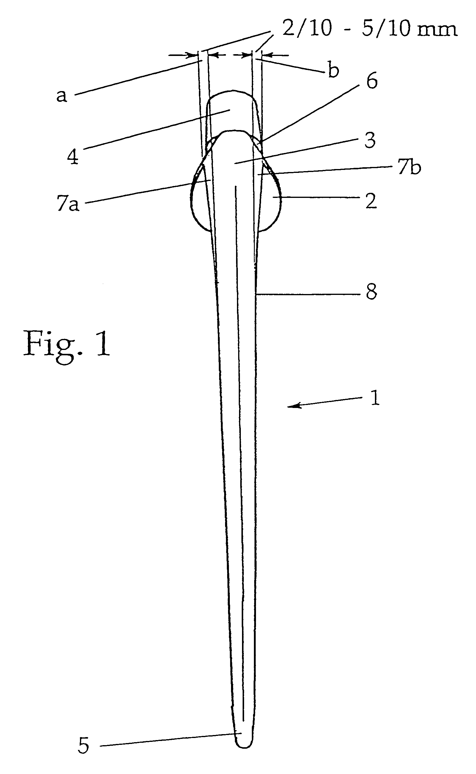
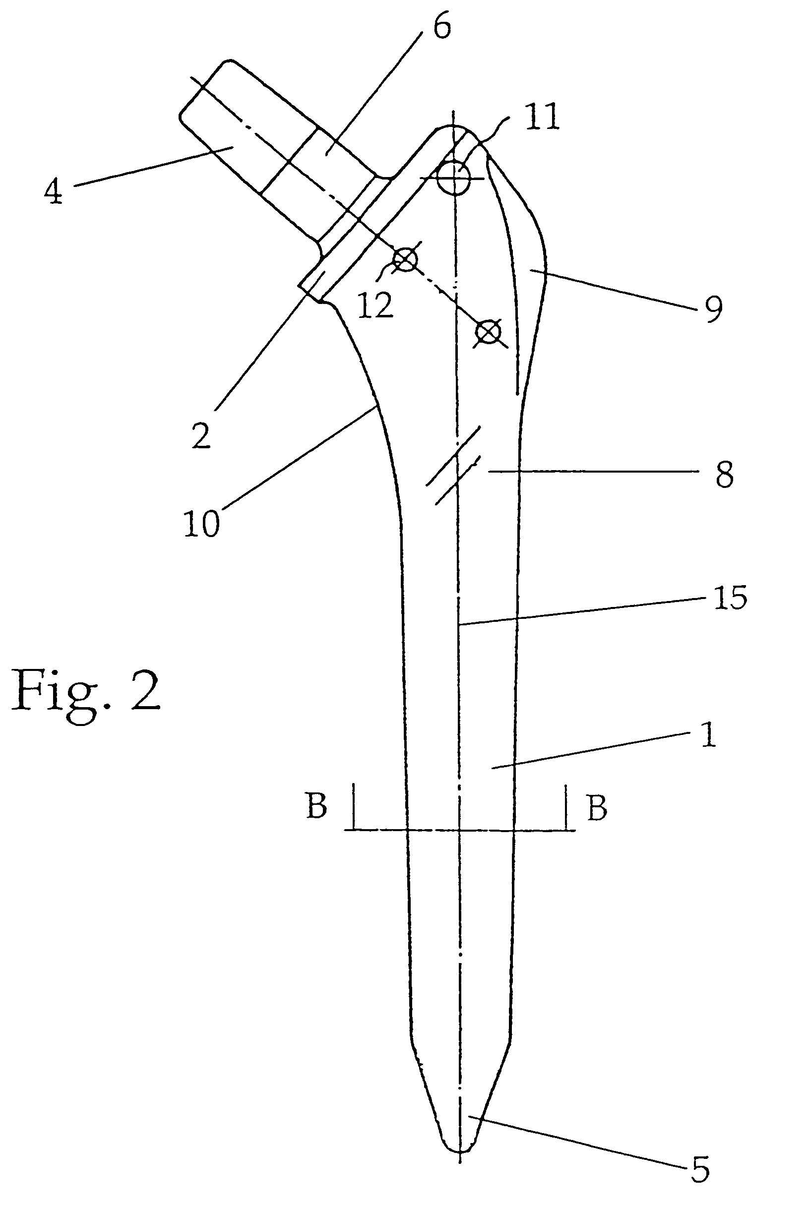
[0028]A shaft 1 shown in FIGS. 1 and 2 serves to anchor a hip-joint prosthesis in the femur. As can be seen in FIGS. 1 and 2, the shaft expands uniformly on all sides in the proximal direction, from the distal end 5 as far as a collar-like projection 2 that separates an anchoring section of the shaft 1 from a prosthesis neck 6. As shown in FIG. 2, proximal to the “cone” the medial narrow side of the shaft is shaped like a continuously curving arch 10, which ends at the above-mentioned projection 2. The reference numeral 3 identifies an upper transition region, the numeral 9 (FIG. 2) a trochanter wing, and the numerals 11 and 12 indicate cross-bores that extend through the shaft from anterior to posterior. These bores have the function of facilitating comparison between X-rays taken at different times. They can also be used to detect a potential displacement of the shaft after it has been in place for a long time. The long axis (longitudinal central axis) of the shaft is identified i...


PUM

PropertyMeasurementUnit
Lengthaaaaaaaaaa
Fractionaaaaaaaaaa
Fractionaaaaaaaaaa

Abstract

A flat shaft of a hip-joint prosthesis for anchoring in a femur. The shaft expands on all sides towards a proximal end from a distal end of the shaft and medially merges with a curved section that is continuous with a prosthesis neck. The shaft is additionally expanded in a proximal region along a proximal direction on at least one of an anterior and posterior surfaces.

Description

BACKGROUND OF THE INVENTION[0001]1. Field of the Invention[0002]The invention relates to a flat shaft of a hip-joint prosthesis for anchoring in the femur according to the precharacterizing clause of claim 1.[0003]2. Description of the Related Art[0004]A shaft of this kind is known from the patent EP 0 032 165 B1. In this known construction the shaft is approximately conically tapered, expanding on all sides from the distal end toward the proximal end, into a region situated at about ⅔ and ¾ of the length of the shaft as measured on its long axis. On the medial narrow side, the conical part of the shaft merges with a continuously curving arch that ends in a collar-like projection. This projection separates a femur-anchoring section of the shaft from a prosthesis neck comprising a peg that tapers conically towards its proximal end, which serves to receive a spherical joint head. The axis of the prosthesis neck intersects the long axis of the shaft at an angle that corresponds substan...

Claims


Application Information

Patent Timeline
IPC IPC(8): A61F2/36A61F2/00A61F2/30
CPCA61F2/30767A61F2/36A61F2/367A61F2/3672A61F2/3676A61F2002/30011A61F2002/30112A61F2002/30113A61F2002/30125A61F2002/30138A61F2002/30153A61F2002/30154A61F2002/30158A61F2002/30159A61F2002/30166A61F2002/30321A61F2002/30785A61F2002/30879A61F2002/30906A61F2002/3092A61F2002/30929A61F2002/3625A61F2002/3631A61F2002/365A61F2002/3668A61F2002/368A61F2230/0004A61F2230/0006A61F2230/0008A61F2230/0017A61F2230/0019A61F2230/0021A61F2230/0026A61F2230/0028A61F2250/0023A61F2250/0025A61F2310/00023A61F2310/00407A61F2310/00796A61F2002/30884
Inventor ZWEYMULLER, KARL
Owner SMITH & NEPHEW ORTHOPAEDICS
Why Eureka
Try Eureka