Ultraviolet disinfecting apparatus

a disinfecting apparatus and ultraviolet light technology, applied in the field of air purification system, can solve the problems of increasing the size, weight, and power of the resulting equipment, and achieve the effect of improving the quality of air

Inactive Publication Date: 2009-03-03
CERINET USA
View PDF17 Cites 54 Cited by
  • Summary
  • Abstract
  • Description
  • Claims
  • Application Information

AI Technical Summary

Problems solved by technology

Common to the prior art UV disinfection systems is overdosage of ultraviolet (UV) radiation to the air being disinfected, which necessarily increases the size, weight, and power of the resulting equipment.

Method used


Image

  • Ultraviolet disinfecting apparatus
  • Ultraviolet disinfecting apparatus
  • Ultraviolet disinfecting apparatus

Examples


Embodiment Construction

Mode(s) for Carrying Out the Invention

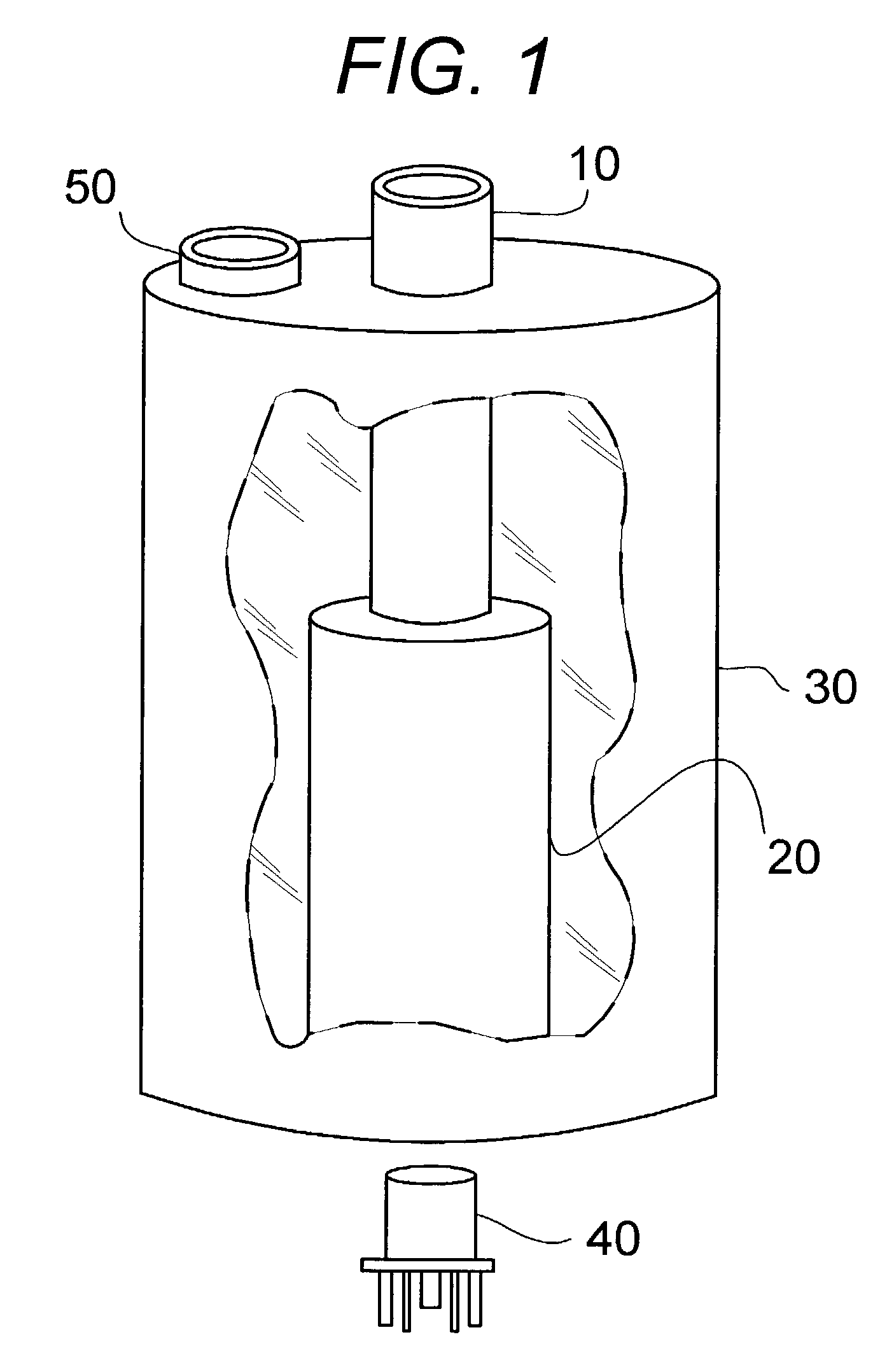
[0016]Referring first to FIG. 1, the basic construction of an ultraviolet (UV) water disinfecting device in accordance with my invention is shown, including a fluid inlet tube 10 that acts as a central light pipe, an optical cladding tube 20 around the lower portion of fluid inlet tube 10 and defining therewith a concentric gap 15, a fluid containment vessel 30, a fluid outlet tube 50, and a high intensity UV lamp 40, such as a flashlamp.

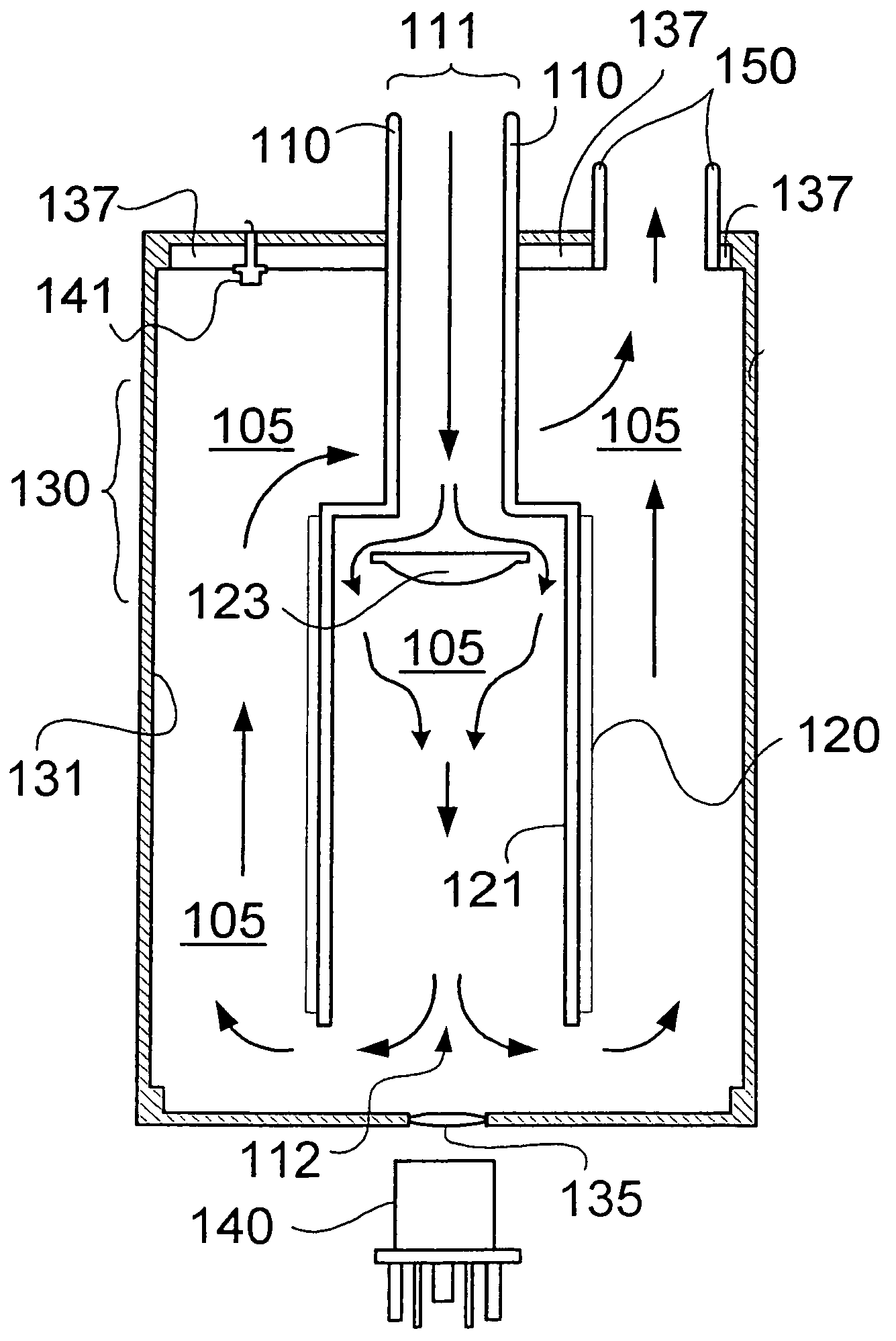
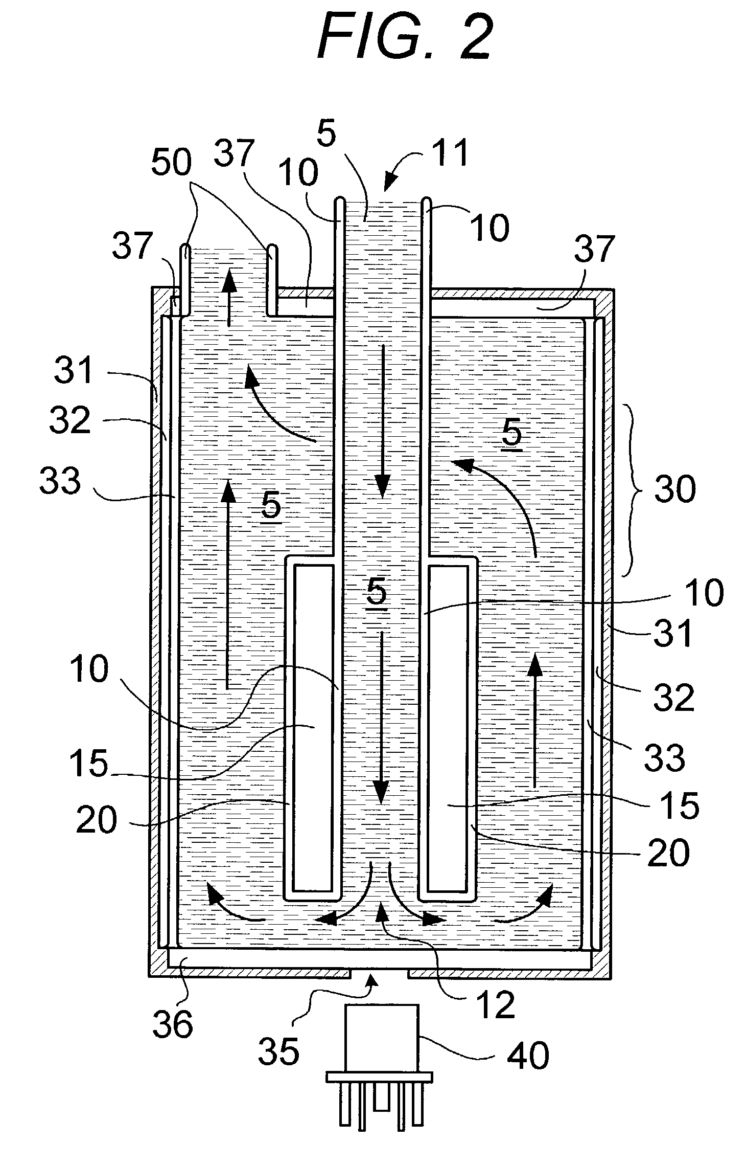
[0017]Referring next to FIG. 2, the fluid containment vessel 30 includes an internal surface configured as an ultraviolet mirror 31; for example, the fluid containment vessel may be constructed from aluminum and the internal surface may be polished aluminum. A fluid 5 to be disinfected, such as water, enters the fluid inlet tube 10 through an entrance end 11. The fluid inlet tube 10 may be manufactured, for example from UV-grade fused silica.

[0018]The fluid 5 travels through the fluid inlet tube 10 towards the h...


PUM

PropertyMeasurementUnit
angleaaaaaaaaaa
refractive indexaaaaaaaaaa
refractive indicesaaaaaaaaaa

Abstract

Ultraviolet radiation is used to disinfect air (105) in a flow tube (110), where the flow tube (110) includes total internal reflecting features (120) on a portion of its external surface and said ultraviolet radiation propagates through a portion of the flow tube via total internal reflection.

Description

RELATED APPLICATIONS[0001]This application is a continuation-in-part of the U.S. patent application Ser. No. 10 / 268,567, filed Oct. 9, 2002, now U.S. Pat. No. 6,773,584, Aug. 10, 2004, and relies on the disclosure of U.S. Provisional Patent Application Ser. No. 60 / 336,381, filed Nov. 2, 2001, both of which are incorporated herein by reference.BACKGROUND OF THE INVENTION[0002]1. Technical Field[0003]This invention relates to an air purification system using intense ultraviolet irradiation to break down chemical bonds in toxic compounds and to de-activate pathogens. The method can also be applied to any mass transport, including the purification of water or other fluids containing naturally occurring toxins or those resulting from biological and chemical agents used in warfare.[0004]2. Background Art[0005]Prior art UV disinfecting systems are typically water disinfecting systems where the water is exposed to UV radiation such that the radiation passes through the water, strikes a refl...

Claims


Application Information

Patent Timeline
Patent Type & Authority Patents(United States)
IPC IPC(8): A61L9/00A61L2/00A62B7/08B01J19/08B03C3/38G01N21/00G01N23/00A61L2/10A61L9/20B01D53/86C02F1/32
CPCA61L2/10A61L9/20B01D53/8675C02F1/325C02F2201/3221C02F2201/3228C02F2201/326F24F2003/1667Y10S422/90Y02A50/20F24F8/22
Inventor SACCOMANNO, ROBERT J.
Owner CERINET USA
Why Eureka
Try Eureka