Unlock instant, AI-driven research and patent intelligence for your innovation.

Piezoelectric resonator and method for manufacturing thereof

a technology of piezoelectric resonators and manufacturing methods, which is applied in the field of piezoelectric resonators, can solve the problems of limiting the size of piezoelectric resonators to some degree, and achieve the effects of reducing the size of piezoelectric resonators

Active Publication Date: 2009-03-03
SEIKO EPSON CORP
View PDF3 Cites 7 Cited by
  • Summary
  • Abstract
  • Description
  • Claims
  • Application Information

AI Technical Summary

Benefits of technology

This design enables a smaller piezoelectric resonator size, reduces electrical disconnection and discharge risks, and increases the area available for the resonator element, allowing for more resonators to be produced from a single substrate.

Problems solved by technology

Thus, miniaturization of the piezoelectric resonator is restricted to some degree.

Method used


Image

  • Piezoelectric resonator and method for manufacturing thereof
  • Piezoelectric resonator and method for manufacturing thereof
  • Piezoelectric resonator and method for manufacturing thereof

Examples


first embodiment

[0042]FIGS. 1A and 1B show a piezoelectric resonator 1 according to a first embodiment of the invention.

[0043]FIG. 1A is a perspective view of the piezoelectric resonator 1 and FIG. 1B is a cross-sectional view taken along a line A-A of FIG. 1A.

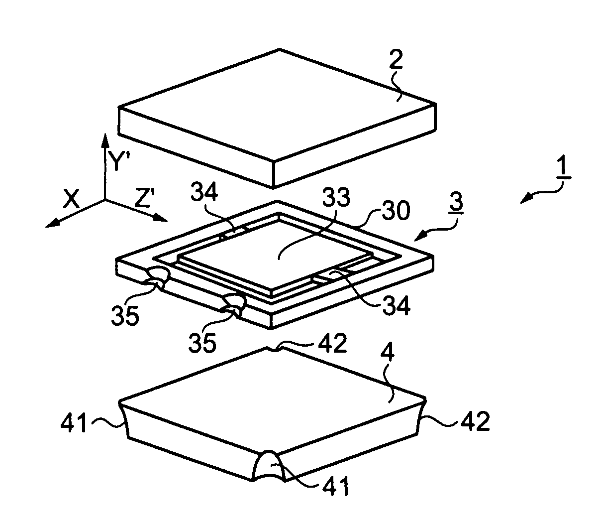
[0044]FIG. 2 is an exploded perspective view of the piezoelectric resonator 1. The piezoelectric resonator 1 includes a lid substrate 2, a resonator substrate 3 and a base substrate 4.

[0045]FIG. 3A a plan view of the resonator substrate 3 seen from the side of the lid substrate 2, FIG. 3B is a plan view of the resonator substrate 3 seen from the side of the base substrate 4.

[0046]Referring to FIGS. 1A and 2, the piezoelectric resonator 1 is constructed such that the base substrate 4 supports the resonator substrate 3, and the lid substrate 2 is stacked thereon. The resonator substrate 3 is sandwiched and bonded between the lid substrate 2 and the base substrate 4.

[0047]The base substrate 4 is a substantially rectangular plate and has four sid...

second embodiment

[0095]FIGS. 8A and 8B show two types of resonator substrates 3 according to a second embodiment of the invention.

[0096]FIG. 8A is a plan view of the resonator substrate 3 seen from the side of the base substrate 4. FIG. 8B is a plan view of another resonator substrate 3 seen from the side of the base substrate 4.

[0097]Referring to FIG. 8A, the support part 34 of the resonator element 33 is arranged along with the frame part 30 on the side of the concave portion 35. Between the resonator element 33 and the frame part 30 a cut-out part 314 is defined.

[0098]The second excitation electrode 32 is provided to the surface of the resonator substrate 3 facing the base substrate 4. Specifically, the second excitation electrode 32 is provided on the resonator element 33, one of the two support parts 34 and the frame part 30 of the resonator substrate 3 facing the base substrate 4. Here, the excitation electrode 32 is not provided in the vicinity of the concave portions 35. Provided in the vici...


PUM

PropertyMeasurementUnit
diameteraaaaaaaaaa
diameteraaaaaaaaaa
diameteraaaaaaaaaa

Abstract

A piezoelectric resonator includes a resonator substrate, a base substrate supporting the resonator substrate, a lid substrate covering a surface of the resonator substrate, the surface being on an opposite side of a surface facing the base substrate, a first excitation electrode formed on the surface of the resonator substrate facing the lid substrate, a second excitation electrode formed on the surface of the resonator substrate facing the base substrate, and a third electrode provided on the surface of the resonator substrate facing the base substrate, the third electrode being electrically connected to the first excitation electrode through a concave portion which is formed on a side surface of the resonator substrate.

Description

BACKGROUND OF THE INVENTION[0001]1. Technical Field[0002]The present invention relates to a piezoelectric resonator used for a small sized electronic apparatus and a method for manufacturing the same.[0003]2. Related Art[0004]The small sized electronic apparatus has been required to be miniaturized further. It is demanded that the piezoelectric resonator becomes smaller which is used for the small sized electronic apparatus.[0005]Here, a resonator element included in the piezoelectric resonator is necessary to have a vibration area as large as possible, because the larger the vibration area is, the smaller the crystal impedance is, allowing the resonator element to vibrate well. Therefore, it is necessary for the resonator element to be contained in a package reduced in size in order to miniaturize the piezoelectric resonator, securing the vibration area of the resonator element. There is a need for an arrangement of an electrode provided in the package to be improved in order to mi...

Claims


Application Information

Patent Timeline
Patent Type & Authority Patents(United States)
IPC IPC(8): H01L41/053H01L41/08H01L41/09H01L41/18H01L41/22H01L41/23H01L41/29H01L41/313H01L41/332H01L41/338H03H3/02H03H9/19
CPCH03H9/0595H03H9/1035Y10T29/42H03H9/19
Inventor TSUCHIDO, KENJI
Owner SEIKO EPSON CORP