Measurement reporting in a telecommunication system

a technology of telecommunication system and measurement, applied in the direction of radio transmission, transmission monitoring, electrical equipment, etc., can solve the problems of reducing system capacity, increasing network resources, and negatively affecting system capacity and network resources

Inactive Publication Date: 2009-03-03
QUALCOMM INC
View PDF17 Cites 27 Cited by
  • Summary
  • Abstract
  • Description
  • Claims
  • Application Information

AI Technical Summary

Benefits of technology

[0140]The measurement reporting scheme according the invention provides flexible means for reporting measurement results. The advantage of the flexibility is that the measurement reporting can be adjusted to provide the network the necessary information while minimizing the amount of radio resources spent for the measurement reporting purposes.

Problems solved by technology

While soft handover improves overall performance it may in some situations negatively impact system capacity and network resources.
This is due to the unnecessary branches between the MS and the base stations in the active set.
On the downlink direction from the base stations to the mobile station, excessive branch reduces system capacity while on the uplink direction from the mobile station to the base stations, it costs more network resources.
When there is one or more dominant beacons, adding an additional weaker branch whose beacon signal is above T1 will not improve performance but will utilize more network resources.
When beacons in the active set are weak, removal a branch, even a weak one, will decrease performance.
However, the more information the mobile station sends the network, the more radio resources are spent.
Thus, the measurement reporting schemes according to prior art are always compromises between the efficiency of the handover algorithms and the usage of radio resources.
As the usage of mobile telecommunication systems and multimedia applications requiring large bandwidths is growing the present methods are no longer sufficient, thus limiting the performance of the mobile telecommunication networks.

Method used


Image

  • Measurement reporting in a telecommunication system
  • Measurement reporting in a telecommunication system
  • Measurement reporting in a telecommunication system

Examples


Embodiment Construction

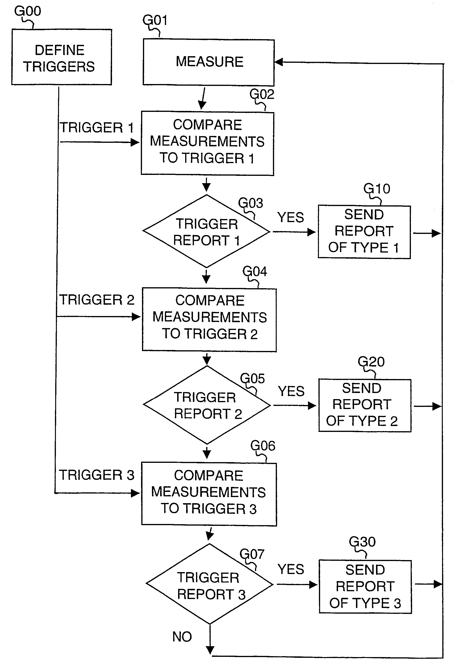
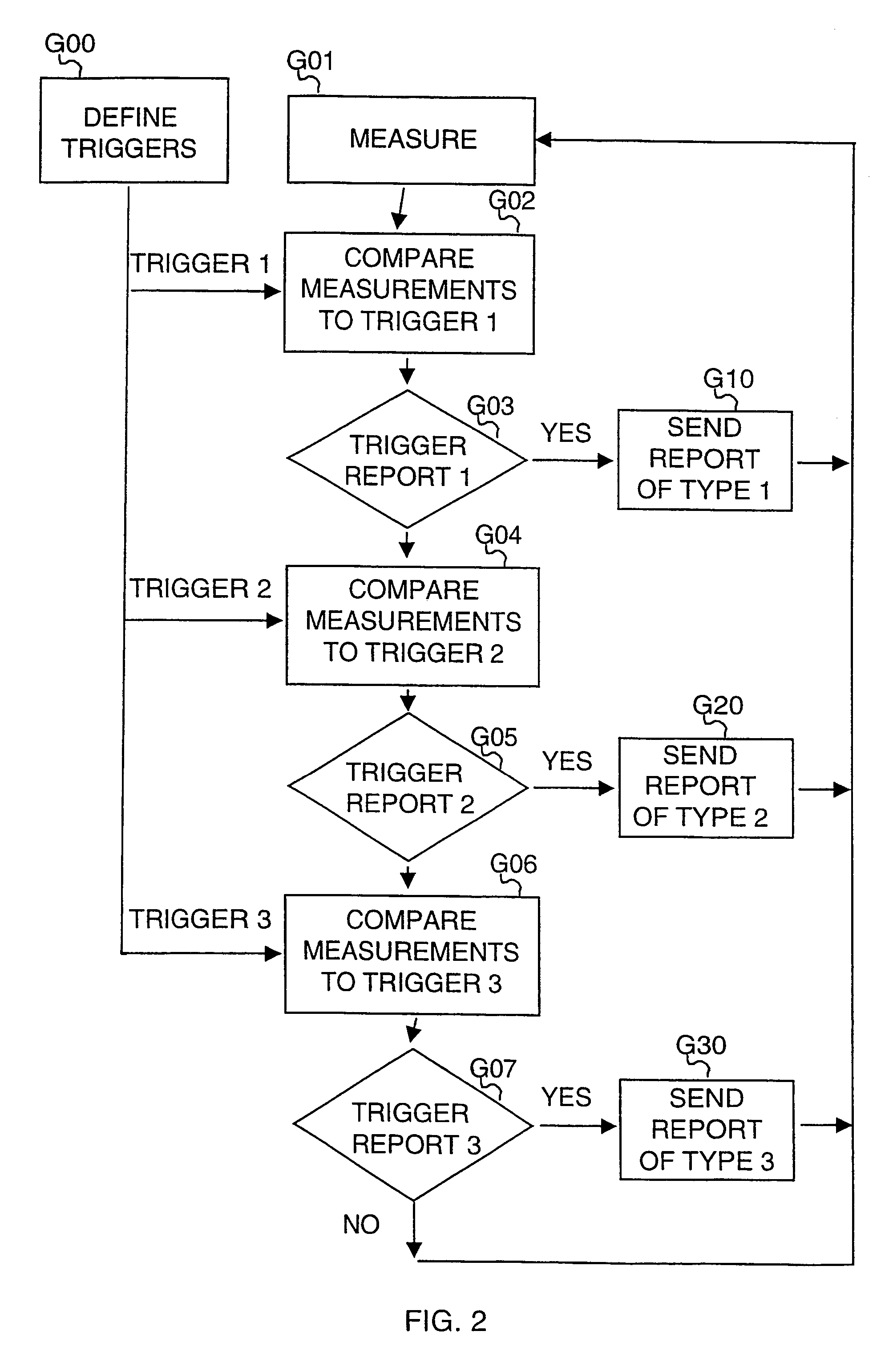
[0038]The basic idea of the invention is presented schematically in FIG. 2. In stage G00, a plurality of triggers is defined in the network. In the exemplary embodiment presented in the figure, three triggers, TRIGGER 1, TRIGGER 2 and TRIGGER 3 are defined. However, is must be noted here that the invention is not limited to the use of exactly three triggers, but the number of triggers may be any number equal to or larger than two. The mobile station is informed about these triggers.

[0039]The mobile station continuously measures the radio signals from the base stations in the neighborhood (stage G01). In these measurements, the mobile acquires information necessary to compare the measurement results to the triggers.

[0040]At stage G02 the measurement results are compared to TRIGGER 1. If the conditions launching the trigger are met (decision stage G03), a measurement report of type 1 is sent to the network at stage G10, and the procedure continues to stage G01. If the conditions are n...


PUM


Abstract

The basic idea of the present invention is to specify at least two different triggers for sending a measurement report from the mobile station to the network. According to the invention, the network specifies the triggers to be used in different measurement report types. The triggers are preferably upper or lower threshold values for parameters of the radio signal. In response to having detected that the measured value has exceeded its upper threshold value or gone under its lower threshold, the mobile station sends the network a measurement report.

Description

CROSS REFERENCE TO RELATED APPLICATION[0001]This application is a continuation of now-allowed U.S. patent application Ser. No. 09 / 622,468, filed Mar. 19, 2001, now U.S. Pat. No. 7,003,290, entitled identical to this application and which entered U.S National Stage from International Application Number PCT / F199 / 00096. That International Application claims priority to Finland Patent Application No. 980357 filed on Feb. 17, 1998. This application claims priority to Feb. 17, 1998 through the above chain of applications, each of which is hereby incorporated by reference.FIELD OF THE INVENTION[0002]This invention concerns reporting of measurements on radio interface in a telecommunication system.BACKGROUND OF THE INVENTION[0003]In mobile telecommunication systems mobile stations MS can use the services provided by the network using radio connections. The radio connection uses the channels of called radio interface between the mobile station and a base station of the mobile telecommunicati...

Claims


Application Information

Patent Timeline
Patent Type & Authority Patents(United States)
IPC IPC(8): H04B17/00H04W36/18H04W36/30
CPCH04W36/30H04W36/18H04L1/0023H04W36/0058H04L1/0026H04L1/0028
Inventor SALONAHO, OSCARSIPILA, KARI
Owner QUALCOMM INC
Why Eureka
Try Eureka