Lever type connector including rotation restricting portion

a technology of rotation restricting portion and lever type, which is applied in the direction of coupling device connection, engagement/disengagement of coupling parts, electrical apparatus, etc., can solve the problems of deformation or damage of the lever or the retained portion of the receptacle connector, insufficient conduction between the terminals, etc., to prevent half-fitting, reduce the cost, and simple structure

Active Publication Date: 2009-03-10
FURUKAWA ELECTRIC CO LTD
View PDF21 Cites 4 Cited by
  • Summary
  • Abstract
  • Description
  • Claims
  • Application Information

AI Technical Summary

Benefits of technology

[0011]According to the first aspect, the lever is prevented from rotating until the connector holder reaches the standby position with a simple structure where the restricting portion is provided. Therefore, there is no need to concern about damage of the lever and the like, and the connector holder and the receptacle holder are firmly coupled, whereby half-fitting is prevented.
[0012]According to the second aspect, in addition to the effect of the first aspect, a rational structure is achieved where the retained portion, which is a multiple force is applied to, serves as a restricting portion as well. Further, a metal mold is easily prepared since there is no need to have a complex and special structure in order to obtain the effect of the first aspect, so that cost will not be increased. Moreover, because the mechanical structure is simplified, there is an advantage that secured mechanical strength of the lever type connector is obtained.

Problems solved by technology

In this case, when the lever is forcibly rotated, a fulcrum retaining portion of the lever or a retained portion of the receptacle connector may be deformed or damaged.
Moreover, the connector and the receptacle connector may be half-fitted, whereby conduction between the terminals may be insufficient.

Method used


Image

  • Lever type connector including rotation restricting portion
  • Lever type connector including rotation restricting portion
  • Lever type connector including rotation restricting portion

Examples


Embodiment Construction

[0016]Hereinafter, an embodiment of the present invention will be explained with reference to the drawings.

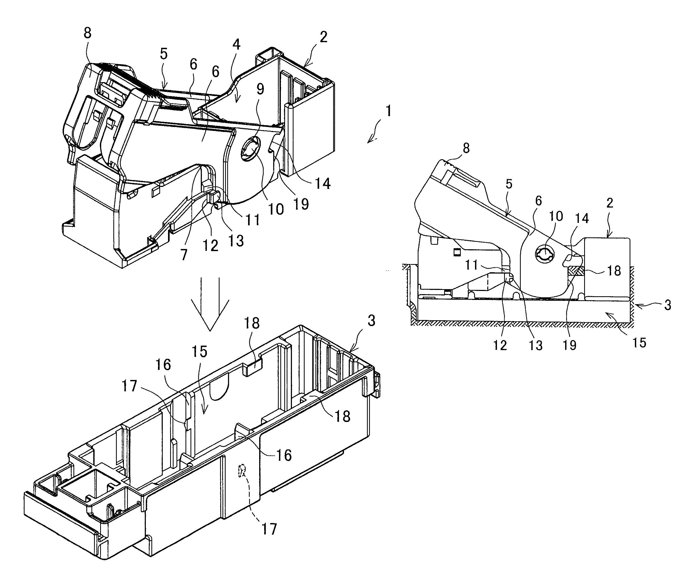
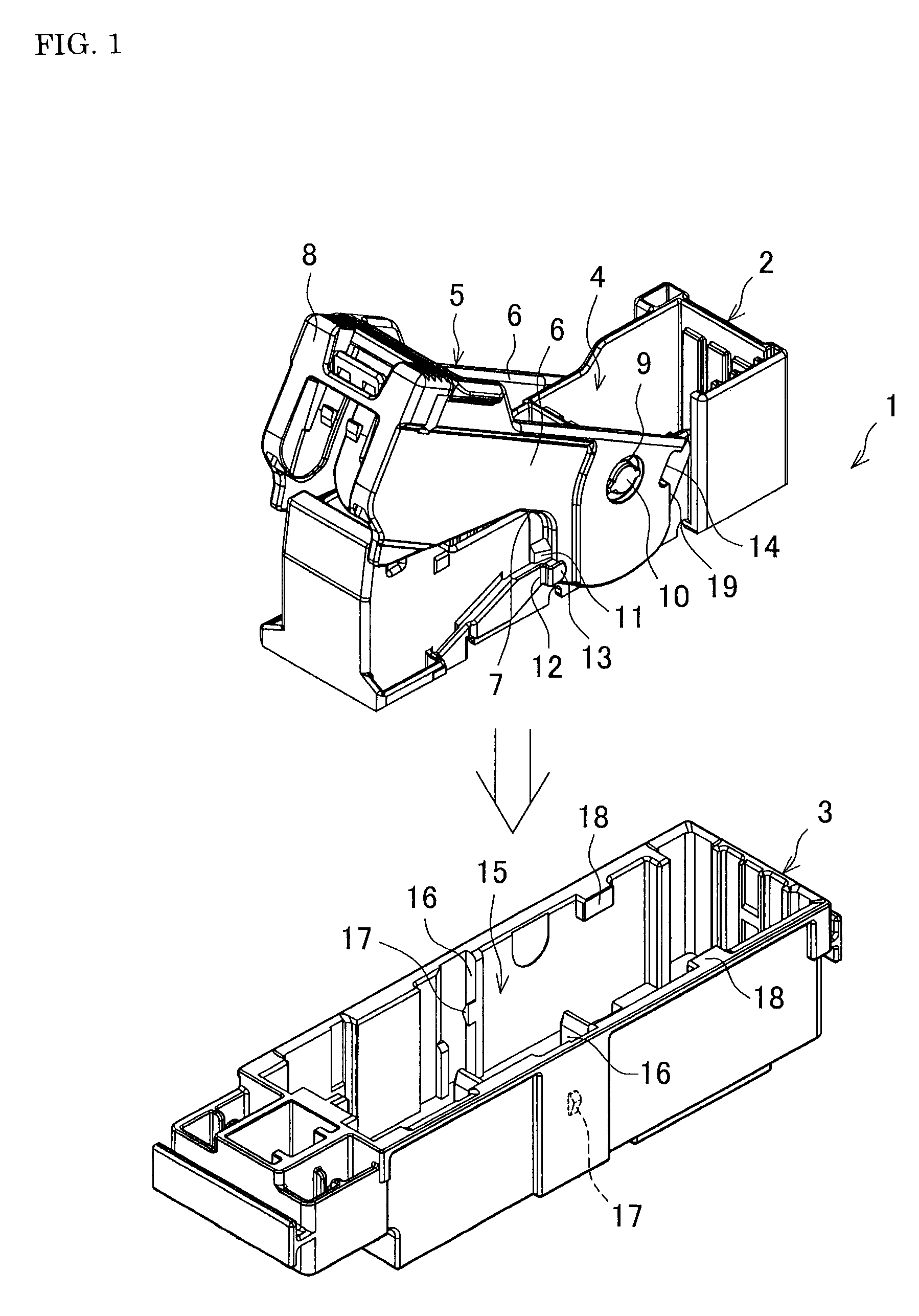
[0017]FIG. 1 is a perspective view of an example of a lever type connector. The lever type connector 1 includes a connector holder 2 and a receptacle connector 3 into which the connector holder 2 is inserted to be fit.

[0018]The connector holder 2 is of an elongate box shape and made of synthetic resin. A receiving portion 4 is defined within the connector holder 2, and in the receiving portion 4 a not shown female connector where a plurality of terminal insertion portions can be incorporated is provided. The reference number 5 denotes a lever which is U-shaped viewed from the above, including a pair of right and left arm plates 6, 6 having a recessed portion 7 at the bottom center thereof, and an operating portion 8 connecting the rear ends of the arm plates 6, 6 (here, the upper right is the front in this figure). A circular projection 10 is provided on a lateral outer surface...


PUM


Abstract

A lever type connector in which a connector holder is reliably fit into a receptacle holder to prevent a half-fitting is provided. In the lever type connector, a restricting recess is provided on the front side of an arm plate of a lever, and below a multiple force recess. When a connector holder is inserted into the receptacle, a rear surface of the restricting recess abuts to a rear surface of a receiving portion to restrict rotation of the lever. Then, when the connector holder is pushed down to the standby position where the receiving portion is inserted into the multiple force recess, the restricting recess is away from the rear surface of the receiving portion, so that restriction of rotation of the lever is cancelled.

Description

[0001]This application claims the benefit of Japanese Patent Application Number 2006-285457 filed on Oct. 19, 2006, the entirety of which is incorporated by reference.BACKGROUND OF THE INVENTION[0002]1. Field of the Invention[0003]The present invention relates to a lever type connector which is used for a branching connection of a wire harness disposed in an automobile, for example.[0004]2. Description of the Related Art[0005]A conventional lever type connector includes a connector holder capable of holding a plurality of terminals, and a receptacle connector capable of holding a terminal corresponding to a terminal of the connector holder, and when the connector holder is fit at a predetermined fitting position, the terminals are connected to each other. The connector holder has a lever which is rotatable in the upper and lower directions.[0006]In this lever type connector, when the lever is rotated after the connector holder is set to a standby position with respect to the recepta...

Claims


Application Information

Patent Timeline
Patent Type & Authority Patents(United States)
IPC IPC(8): H01R13/62
CPCH01R13/62955
Inventor TAJIRI, YOJIYOSHIDA, TOSHIHIROSURUGA, YASUHARUTAKEDA, KATSUNORIWATANABE, TAKESHIKOBAYASHI, HIROSHI
Owner FURUKAWA ELECTRIC CO LTD
Why Eureka
Try Eureka