Method for manufacturing an electric conductor for electrodes

a technology of electric conductor and electrode, which is applied in the manufacture of electrode systems, electric discharge tubes/lamps, cell components, etc., can solve the problems of insufficient improvement of performance and limitations of pan carbon fiber on cell performance improvement, and achieves improved remarkably generating efficiency of cells, reduced felt density, and increased volume of pores

Active Publication Date: 2009-03-10
FUJI CORP
View PDF5 Cites 0 Cited by
  • Summary
  • Abstract
  • Description
  • Claims
  • Application Information

AI Technical Summary

Benefits of technology

[0026]An electric conductor for electrodes obtained by a method of the present invention has lower felt density and larger number and volume of pores than that of a standard carbon fiber. When the conductor of the present invention is therefore applied to a secondary or fuel cell or the like, such as a sodium-sulfur cell or battery, it can be impregnated with larger amount of cathodic reactant such as molten sulphur and improves remarkably generating efficiency of the cell. The conductor of the present invention has a great number of pores between each fibers and high degrees of fiber orientation, and consequently the problem of blocking decreases and internal resistance of sodium-sulfur cell or the like falls further down as compared with a standard carbon fiber felt, in a case that it is used for a secondary battery.
[0027]In a felt precursor of the present invention, usage of a comparatively expensive flame-resistant fiber is few so that a reduction in expenses for the electric conductor can be achieved, even if the conductor has the given thickness and density. Since the felt precursor contains an organic fiber that incinerates while baking, and thus it rises in baking efficiency to the electric conductor, considerable reduction in costs is achieved in this respect.

Problems solved by technology

The felt made of a PAN carbon fiber has limitations on improvement of cell performance as a electric conductor when being applied alone, and also it is not enough to improve the performance in the felt even if α-alumina powder is scattered.

Method used


Image

  • Method for manufacturing an electric conductor for electrodes

Examples


example 2

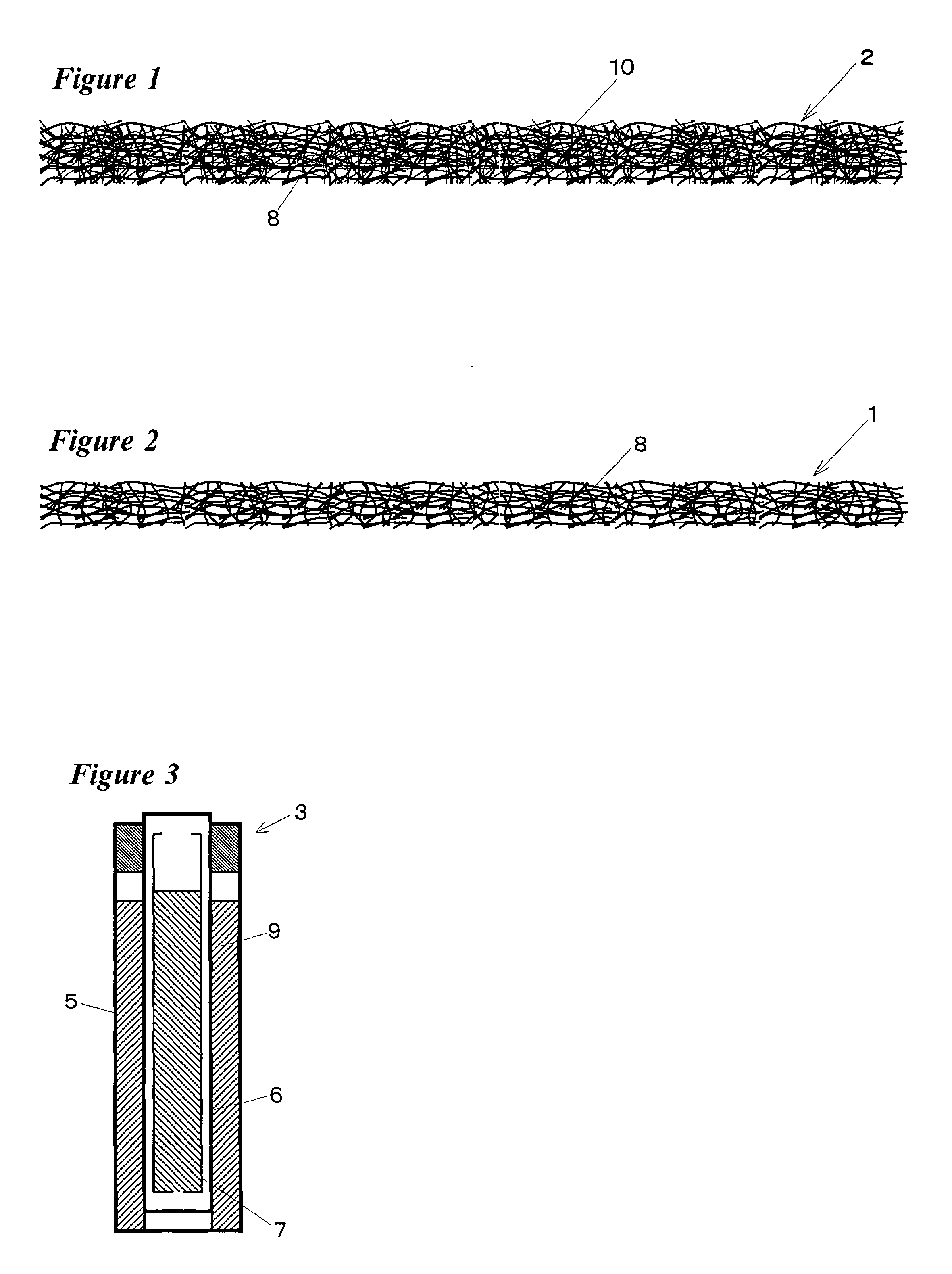
[0040]With the flame-resistant PAN fiber 8 applied in Example 1, there was mixed 10% in weight of polypropylene staple having a fineness of 7.7 dtex and 32 mm in length to form a lap by carding with a well-known carder. Suitable number of the lap thus obtained was layered and then a felt precursor 2 was prepared by needle-punching from one side thereof. The felt precursor 2 has a density of 0.148 g / cm3 and a degree of fiber orientation of 38%.

[0041]The felt precursor 2 was also baked at about 1600° C. to carbonize the flame-resistant PAN fiber 8 and incinerate the polypropylene staple. As this result, solid of the polypropylene staple was almost transpired and thereby the felt 2 was voided of the staple to yield a felt-type conductor 1 for electrodes. A density of the electric conductor 1 was diminished to 0.099 g / cm3. In the conductor 1, the felt density thereof lowered and pores thereof increased as compared with a normal felt made of a carbon fiber. When the conductor 1 was appli...

example 3

[0042]With the flame-resistant PAN fiber 8 applied in Example 1, there was mixed 5% in weight of polypropylene staple having a fineness of 4.4 dtex and 30 mm in length. By the same treatment as Example 1, there was prepared a felt precursor 2 having a density of 0.154 g / cm3 and a degree of fiber orientation of 33%.

[0043]The felt precursor 2 was baked to carbonize the flame-resistant PAN fiber 8 and incinerate the polypropylene staple. As this result, solid of the polypropylene staple was almost transpired and thereby the felt 2 was voided of the staple to yield a felt-type conductor 1. A density of the electric conductor 1 was 0.101 g / cm3. In the conductor 1, the felt density thereof lowered and pores thereof increased as compared with a normal felt made of a carbon fiber. When the conductor 1 was applied to sodium-sulfur cell, it held much melted sulfur and generating efficiency of sodium-sulfur cell was improved.

example 4

[0044]With the flame-resistant PAN fiber 8 applied in Example 1, there was mixed 5% in weight of polyester fiber having a fineness of 6.6 dtex and 38 mm in length, instead of polypropylene staple. By the same treatment as Example 1, there was prepared a felt precursor 2 having a density of 0.142 g / cm3 and a degree of fiber orientation of 31%.

[0045]The felt precursor 2 was baked to carbonize the flame-resistant PAN fiber 8 and incinerate the polyester fiber. As this result, solid of the polyester fiber was almost transpired and thereby the felt 2 was voided of the polyester fiber to yield a felt-type conductor 1 for electrodes. A density of the electric conductor 1 was 0.095 g / cm3. In the conductor 1, the felt density thereof lowered and pores thereof increased as compared with a normal felt made of a carbon fiber. When the conductor 1 was applied to sodium-sulfur cell, it held much melted sulfur and generating efficiency of sodium-sulfur cell was improved.


PUM

PropertyMeasurementUnit
lengthaaaaaaaaaa
densityaaaaaaaaaa
electric resistanceaaaaaaaaaa

Abstract

An electric conductor for electrodes composed of a carbon fiber felt has low felt density and a great number of pores so that it can retain a cathodic reactant such as molten sulphur. The electric conductor is manufactured by forming a lap by mixing and locking together relatively large amount of a flame-resistance fiber and relatively small amount of an organic fiber, orienting fibers of the layered lap in the direction of a thickness by needle-punching to felt the layered lap and baking the felt thus obtained at 1100 to 2000° C. whereby the flame-resistant fiber is carbonized and then the organic fiber is so incinerated that solid thereof is almost transpired.

Description

TECHNICAL FIELD[0001]The present invention relates to a felt precursor of an electric conductor for electrodes, which can retain a large amount of a cathodic reactant such as melted sulfur by having pluralities of pores, and a method for preparing the electric conductor composed of a felt of made a carbon fiber having low density.BACKGROUND ART[0002]Out of consideration for environmental pollution, there has been now requested clean energy in which exhaust of carbon dioxide is low as for usage of electricity. A power storage system has been put to practical use, in which electric power generated during low power consumption is charged in a secondary cell or battery and is consumed when necessary, and also the development of a fuel cell has been advanced promptly. The fuel cell is a system that allows hydrogen extracted from natural gas or the like to react electrochemically with atmospheric oxygen to generate electricity. The heat of about 100° C. wasted during electricity generatio...

Claims


Application Information

Patent Timeline
Patent Type & Authority Patents(United States)
IPC IPC(8): D01F9/12C01B31/02D04H1/4242D04H1/43D04H1/4374H01B13/00H01M10/39
CPCD04H1/42D04H1/46D04H1/74H01M4/663H01M4/80H01M4/801H01M4/806Y10T428/24992Y02E60/10Y02E60/50H01M10/39H01M4/96D04H1/498
Inventor AOKI, KATSUJI
Owner FUJI CORP
Why Eureka
Try Eureka