X-ray CT apparatus and medical data communication link system

a technology of x-ray ct apparatus and x-ray ct, which is applied in the field of medical data communication link system and x-ray ct apparatus, can solve the problems of increasing the width of the system, increasing the space required for installation of the x-ray ct apparatus, and inability to meet the above requirements, etc., and achieves the effect of high data rate transmission

Inactive Publication Date: 2009-03-10
TOSHIBA MEDICAL SYST CORP
View PDF22 Cites 14 Cited by
  • Summary
  • Abstract
  • Description
  • Claims
  • Application Information

AI Technical Summary

Benefits of technology

[0010]The purpose of this embodiment is to provide a medical data communication link system and an X-ray CT apparatus using the system thereof, which are constructed for simultaneous communication through a plurality of channels without increasing the installation space in order to increase the volume of data for simultaneous communication.
[0013]A signal generation device provided to the rotating frame of an X-ray CT apparatus outputs dividing data into a plurality of channels. A plurality of transmission medium are provided to the rotating frame along the circumference of the rotating frame, while a plurality of receiving medium are provided to the stationary frame such that said receiving medium are provided in intervals along the circumference of the rotating frame. A switching device provided between the signal generation device and the transmission medium assigns the data of a plurality of channels output from the signal generation device to each transmission medium. At the passing of an interval between the two adjacent transmission medium, the switching device switches the data for transmission to the two transmission medium to the data of the same channel. Due to this switching, the signal distributed to each channel containing the data from the X-ray detector can be continuously transmitted to the stationary frame without loss.
[0015]According to the above compositions, the medical data from the rotating frame such as the large amount of data detected by the X-ray detector can be divided into a signal of a plurality of channels and the image at the stationary frame can be simultaneously transmitted to the reconstitution process. That is, a large amount of data can be divided in a plurality of channels and transmitted in parallel, enabling high data rate transmission.

Problems solved by technology

However, because communication occurs through one channel, the above requirements cannot be satisfied.
As clearly shown in FIG. 3, however, this method increases the width of the system, thus having a disadvantage of increasing the space required for installation of the X-ray CT apparatus.
However, increasing the transmission speed creates many problems to be solved, such as difficulty in obtaining the same phase (propagation delay) as explained above, and therefore is judged to be impractical.

Method used


Image

  • X-ray CT apparatus and medical data communication link system
  • X-ray CT apparatus and medical data communication link system
  • X-ray CT apparatus and medical data communication link system

Examples


first embodiment

of the Medical Data Communication Link System

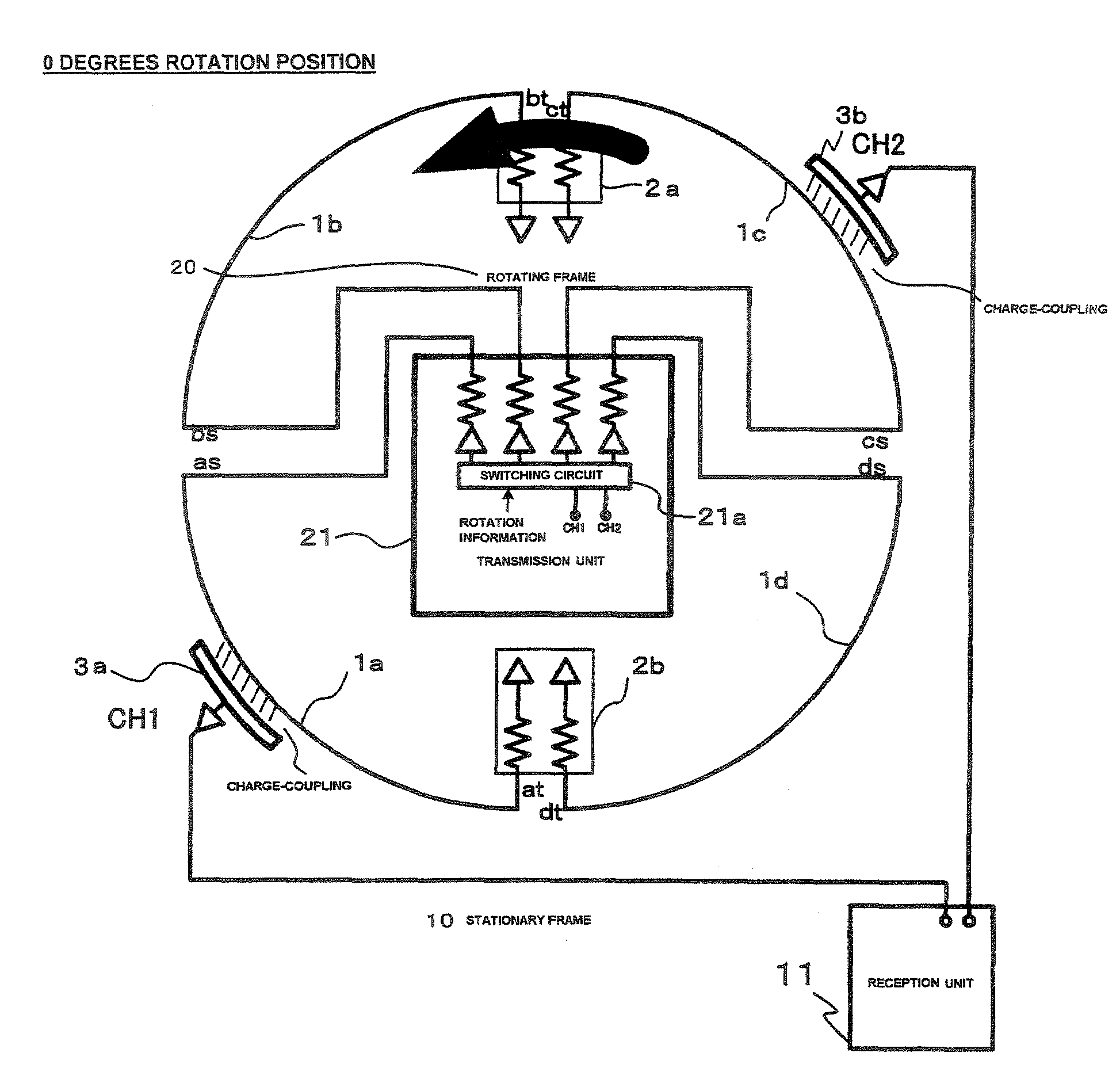
[0035]FIG. 4 typically shows the constitution of the rotating frame 20 and the stationary frame 10 at the initial stage of rotation (with an angle of rotation of 0 degrees for example). For the rotating frame 20, a transmission medium 1a, transmission medium 1b, transmission medium 1c and transmission medium 1d (hereinafter, “Transmission medium 1” indicates any of the medium individually) are provided in a line in intervals around the circumference of the rotating frame 20. Each transmission medium 1 forms a strip line extending around the circumference. On the stationary frame 10, a receiving medium 3a and a receiving medium 3b (hereinafter “Receiving medium 3” indicates any of the medium individually) are mounted.

[0036]The interval between the transmission medium 1 (between ends as—bs, ends bt—ct, ends cs—ds, and ends dt—at in FIG. 4) is shorter than each length of the receiving medium 3a and the receiving medium 3b around the circumfe...

second embodiment

of the Communication System

[0055]FIGS. 10 and 11 show an example expanding up to three channels. The conditions for this expansion include a number of receiving medium 3 more than N components and the number of transmission medium 1 more than 2N components relative to the channel of several N components.

[0056]FIG. 10 shows three-channel communication, wherein the number was increased proportionate to the number in the composition / action of the first embodiment for two-channel communication. Accordingly, the dimensions, arrangement, and action in response to the rotation angle become smaller according to the number of channels; however, the technological concept is the same, for which a brief explanation is given below.

[0057]FIG. 10 shows the typical constitution of a rotating frame 20A with a rotation angle of 0 degrees and the stationary frame 10A. At the rotating frame 20A, the 6 transmission medium 1e-1k (excluding 1i) (hereinafter, “Transmission medium 1” indicates any of the me...

third embodiment

of the Communication System

[0063]FIG. 12 provides an example of an embodiment enabling three-channel communication shown in FIG. 10, wherein the receiving medium 3e is excluded to modify into two-channel communication. The third embodiment shows that N channel communication is possible if the number of transmission medium 1 counts for more than M components exceeding 2N components. FIG. 12 is an example wherein the number of transmission medium 1 is counted as 6 components (M=6) with two channels (N=2). M=5, 7, etc. is also possible with N=2.

[0064]In FIG. 12, the switching circuit 22a may be switched in the same way as in FIG. 11. Only the signal from channel CH3 is not transferred. When a signal generated in the signal generation of channel CH3 by the transmission unit 22 will be unused, the signal from CH3 shown in FIG. 11 will be eliminated, but this is acceptable; however, the signal from CH3 shown in FIG. 11 may equal the channel signal from the adjacent transmission medium 1 f...


PUM


Abstract

A receiving medium comprising N components is assigned to a channel comprising N components respectively and provided along the circumference around which a rotating frame rotates. At a position facing the receiving medium corresponding to the rotation, the transmission medium of M components (M≧2N, N represents an integer more than 2) are arranged separately in a line along the circumference of the rotating frame. A signal generation device produces the signal containing data relating to an object obtained by detection of the X-ray detector device. When the transmission medium is rotated according to the carrier signal to face any of the receiving medium, a switching device transmits the signal from the channel to one of the corresponding receiving medium. When the interval between the two adjacent transmission medium passes through the receiving medium, the signal from the same channel may be transmitted to the two adjacent transmission medium.

Description

BACKGROUND OF THE INVENTION[0001]1. Field of the Invention[0002]The field of the present invention relates to a medical data communication link system and an X-ray CT apparatus (or X-ray diagnosis apparatus) which communicate between a rotating frame that takes radiographic image while rotating and a stationary frame that processes the image data received from the rotating frame. In particular, it relates to communication technology relating to the processing of large amounts of data at a high data rate.[0003]2. Description of the Related Art[0004]As shown in FIG. 1(A), the entire constitution of a conventional X-ray CT apparatus is roughly divided into a rotating frame 200, stationary frame 100 (the combination of the rotating frame 200 and the stationary frame 100 is sometimes referred to as gantry) and a console 300. The rotating frame 200 opens to accommodate an object. The rotating frame 200 is constituted such that it can rotate around the object by a rotation-driving device 2...

Claims


Application Information

Patent Timeline
Patent Type & Authority Patents(United States)
IPC IPC(8): H05G1/08H05G1/60
CPCA61B6/4233A61B6/56
Inventor NAKAGAWA, SHOUICHIYAMASHITA, MICHIHIRO
Owner TOSHIBA MEDICAL SYST CORP
Why Eureka
Try Eureka