Head-moving razor

a head-moving and razor technology, applied in the direction of metal working devices, etc., can solve the problems of excessive increase of the width of the grip part, limited cradle head pivoting movement, and restricted angular distance range of the cradle head

Inactive Publication Date: 2009-03-17
OH TAE JUN
View PDF30 Cites 24 Cited by
  • Summary
  • Abstract
  • Description
  • Claims
  • Application Information

AI Technical Summary

Benefits of technology

[0010]Therefore, the present invention has been made in view of the above problems, and it is an object of the present invention to provide a head-moving razor having a movable head wherein the structure of the movable head is relatively simple, and the movable head is brought into wide and smooth contact with the skin of a user when the user performs a shaving operation.

Problems solved by technology

As a result, the grip part must be wide, which is an obstruction to manufacturing a razor having a size enough for a user to comfortably hold.
However, the reduced width of the grip part limits the pivoting movement of the motor, and therefore, the pivoting movement of the cradle head is also limited.
Consequently, the angular distance range of the cradle head is restricted.
Otherwise, the width of the grip part may be excessively increased.
Specifically, the cradle head is pivoted about the axis when the razor is uprightly erected, and the opposite-side torque obstructs the pivoting movement of the cradle head.
As a result, it is not easy to pivot the cradle head over a wide range.
Consequently, it is required that the user raise his elbow to shave his face such that the cradle is brought into smooth contact with several facial regions of the skin, and therefore, fatigue is accumulated.
This problem is caused by the conventional razors disclosed in the above-described three Japanese Unexamined Patent Publications.

Method used


Image

  • Head-moving razor
  • Head-moving razor
  • Head-moving razor

Examples


Embodiment Construction

[0023]Now, preferred embodiments of the present invention will be described in detail with reference to the accompanying drawings.

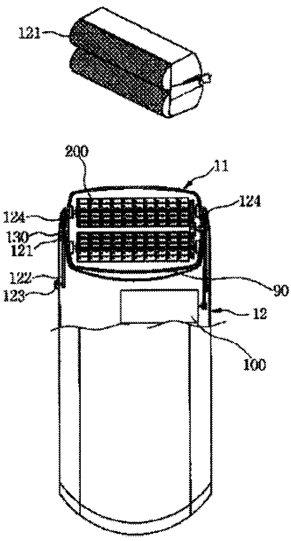
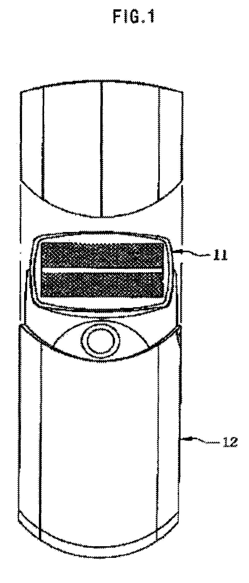
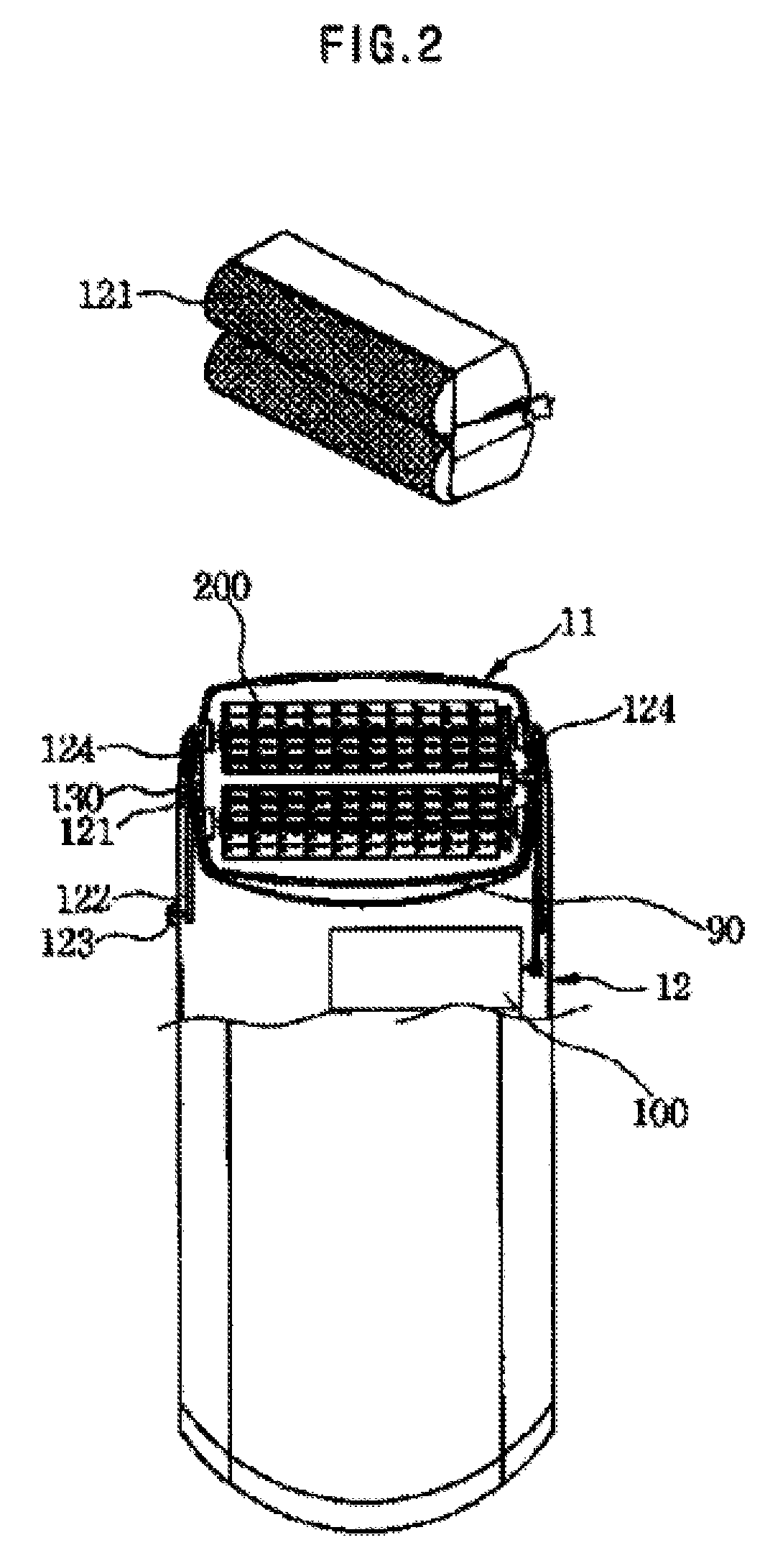
[0024]FIG. 1 is a front view illustrating a head-moving razor according to the present invention, FIG. 2 is a front view, partially in section, schematically illustrating the structure of a head part of the head-moving razor according to the present invention, including a perspective view of the head part, FIG. 3 is a sectional view illustrating the drive structure of the head-moving razor according to the present invention, FIG. 4 is a perspective view illustrating, in detail, components constituting the drive structure of the head-moving razor according to the present invention, FIG. 5 is a view illustrating a drive unit for angularly moving the head part of the head-moving razor according to a preferred embodiment of the present invention, FIG. 6 is a view illustrating a drive unit for angularly moving the head part of the head-moving razor according t...


PUM


Abstract

Disclosed herein is a head-moving razor having a movable head. The head-moving razor includes a head part, which has a drive motor and press blades, and a body part. The head part is movable relative to the body part. The body part is provided at the upper end thereof with a space part, which is defined between the upper surface of the body part and the lower surface of the head part. The upper surface of the body part is spaced a predetermined distance from the lower surface of the head part. The body part is also provided at the upper end thereof with supporting walls, which are protruded upward from the space part. The head part is attached to the supporting walls of the body part such that the head part can be moved a predetermined angular distance. The head part is smoothly moved a predetermined angular distance according to the movement of the hand of a user. Consequently, the cutting force of the head-moving razor is improved, and the smooth shaving operation of the head-moving razor is accomplished.

Description

BACKGROUND OF THE INVENTION[0001]1. Field of the Invention[0002]The present invention relates to a head-moving razor having a movable head, and, more particularly, to a head-moving razor including a head part, which has a drive motor and press blades, and a body part, the head part being movable relative to the body part, wherein the body part is provided at the upper end thereof with a space part, which is defined between the upper surface of the body part and the lower surface of the head part, the upper surface of the body part being spaced a predetermined distance from the lower surface of the head part, and the body part is also provided at the upper end thereof with supporting walls, which are protruded upward from the space part, the head part being attached to the supporting walls of the body part such that the head part can be moved a predetermined angular distance.[0003]2. Description of the Related Art[0004]A razor having a cradle shaving head is known as a conventional a...

Claims


Application Information

Patent Timeline
Patent Type & Authority Patents(United States)
IPC IPC(8): B26B19/14
CPCB26B19/048B26B19/38B26B19/3853B26B19/14B26B19/16
Inventor OH, TAE-JUN
Owner OH TAE JUN
Why Eureka
Try Eureka