
Phase-shifting mask for equal line/space dense line patterns

a phase shift mask and dense line pattern technology, applied in the field of phase shift masks, can solve problems such as destructive interference and image contrast, optical proximity correction (opc) techniques suffer from transmission imbalance, and the pitch between adjacent micro features of the device such as the pitch of word lines shrinks dramatically

Active Publication Date: 2009-03-17
NAN YA TECH
View PDF8 Cites 109 Cited by
  • Summary
  • Abstract
  • Description
  • Claims
  • Application Information

AI Technical Summary

Benefits of technology

The invention is a phase-shifting mask that solves problems in current masks by providing a new design that allows for equal line / space, small pitched, dense line patterns. The mask includes a transparent substrate, columns of first phase-shifting line patterns, and columns of second phase-shifting line patterns. The first phase-shifting line patterns have alternating clear regions and opaque areas, while the second phase-shifting line patterns are 100% light transmittable. The mask also includes a partially shielded mesa line pattern and a clear recessed line pattern, which have the same line width and a phase difference of 180 degrees. The technical effects of this invention include improved pattern accuracy and reduced blurring, resulting in improved image quality.

Problems solved by technology

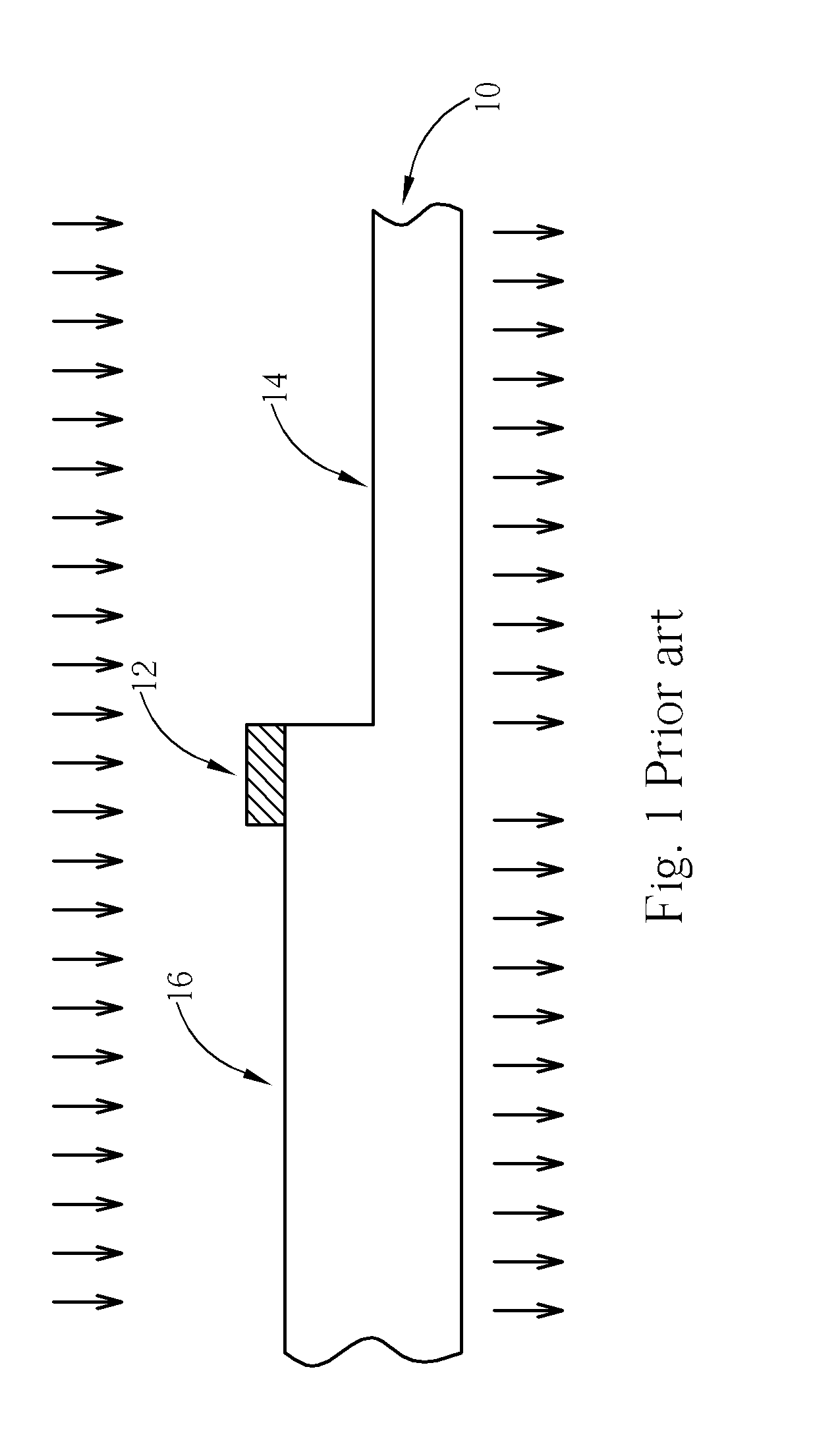
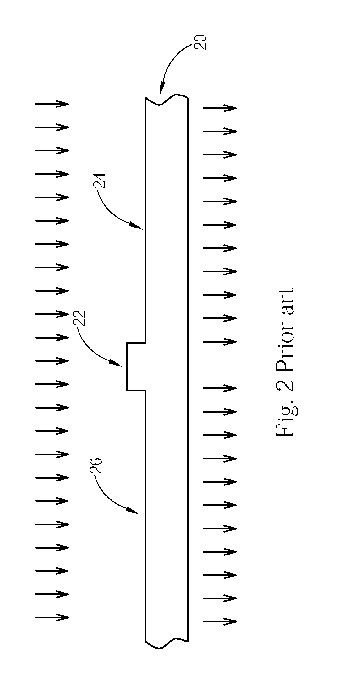
Therefore, light that passes through the transparent region 14 has a 180-degree phase shift relative to light that passes through the thicker transparent region 16, which results in destructive interference and image contrast.
However, this optical proximity correction (OPC) technique suffers from transmission imbalance occurred in phase shifted and non-phase-shifted regions and other flaws caused by alt-PSM.
However, with the increase of packing density of devices such as dynamic random access memory (DRAM) devices, a pitch between adjacent micro features of the device such as word line pitch shrinks dramatically.
Therefore, the prior art chromeless phase-shifting mask fails to transfer the dense pattern.

Method used


Image

  • Phase-shifting mask for equal line/space dense line patterns
  • Phase-shifting mask for equal line/space dense line patterns
  • Phase-shifting mask for equal line/space dense line patterns

Examples


Embodiment Construction

[0029]In describing the preferred embodiment of the present invention, reference will be made herein to FIGS. 4-13 of the drawings, wherein like numerals designate like components, areas or regions. Features of the invention are not drawn to scale in the drawings.

[0030]The present invention pertains to an improved phase-shifting mask (PSM), which is capable of solving equal line / space, small pitched, dense line patterns such as word lines or gate conductors of trench-capacitor dynamic random access memory (DRAM) devices having critical line width that is less than or equal to 100 nanometers. The critical dimension (CD) uniformity of the resultant equal line / space dense line pattern transferred from the PSM of this invention to a photoresist film coated on a wafer is also enhanced.

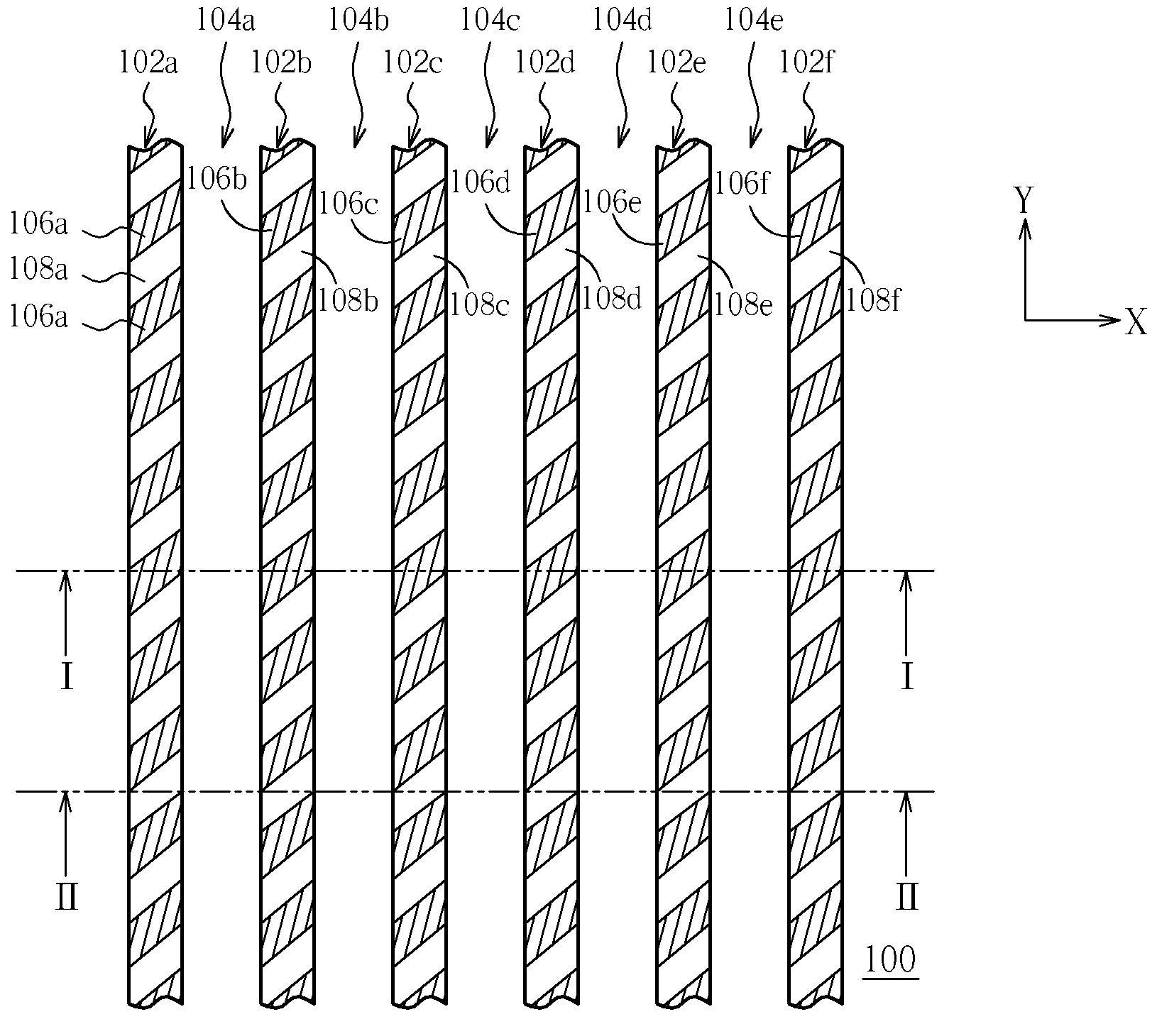
[0031]Please refer to FIGS. 4-7, wherein FIG. 4 is a plan view of a portion of the layout of a PSM in accordance with one preferred embodiment of this invention; FIG. 5 is a schematic, cross-sectional view ...


PUM

PropertyMeasurementUnit
widthaaaaaaaaaa
transparentaaaaaaaaaa
transmittanceaaaaaaaaaa

Abstract

A phase-shifting mask suited for equal line / space, small pitched, dense line pattern is disclosed. The phase-shifting mask includes a transparent substrate, a partially shielded mesa line pattern of first phase formed on the substrate, and a 100% clear recessed line pattern of second phase etched into the substrate and is disposed right next to the partially shielded mesa line pattern. The partially shielded mesa line pattern has a plurality of alternating 45-degree, oblique areas and 100% transmittance clear regions of the first phase. The partially shielded mesa line pattern and the clear recessed line pattern have the same line width. The light that passes through the clear regions of the first phase and the light that passes through the clear recessed line pattern of second phase have a phase difference of 180 degree.

Description

BACKGROUND OF INVENTION[0001]1. Field of the Invention[0002]The present invention relates to a phase-shifting mask (PSM), and more particularly, to a PSM that is capable of generating equal line / space dense line patterns with enhanced critical dimension (CD) uniformity, and lithographic method thereof.[0003]2. Description of the Prior Art[0004]Lithography processing, which is an essential technology when manufacturing integrated circuits, is used for defining geometries, features, lines, or shapes onto a die or wafer. In the fabrication of integrated circuits, lithography plays an important role in limiting feature size. By using lithography, a circuit pattern can be precisely transferred onto a die or wafer. Typically, to implement the lithography, a designed pattern such as a circuit layout pattern or an ion doping layout pattern in accordance with a predetermined design rule is created on one or several mask in advance. The pattern on the mask is then transferred by light exposur...

Claims


Application Information

Patent Timeline
Patent Type & Authority Patents(United States)
IPC IPC(8): G03F1/00
CPCG03F1/0053G03F1/28
Inventor HUNG, YUNG-LONGWU, YUAN-HSUN
Owner NAN YA TECH
Learn More