Automatically balanced sensing device and method for multiple capacitive sensors

a capacitive sensor, automatic balance technology, applied in the field of electrical circuits, can solve problems such as non-uniform response, easy disturbance of imbalanced sensitivity, and circuits susceptible to invalid readings

Active Publication Date: 2009-03-17
MONTEREY RES LLC
View PDF32 Cites 106 Cited by
  • Summary
  • Abstract
  • Description
  • Claims
  • Application Information

AI Technical Summary

Problems solved by technology

A typical conventional switch can use a single sensor, which can make the circuit susceptible to invalid readings due to movement of other capacitive bodies near the single sensor.
These conventional algorithms can use curve-fitting or centroid calculations that can be easily disturbed by imbalanced sensitivity.
Thus, differences in capacitance of switches can lead to non-uniform response.
Disadvantages of both of conventional methods can be that they are cumbersome and difficult to use.
The conventional solution of mechanically balancing the capacitive load on each switch can be a difficult analysis step, and often requires multiple board layout attempts to make a particular design work.
The other conventional solution of testing on the manufacturing line to determine a correction factor for each switch can be expensive and difficult.
In addition, a conventional solution of measuring a sample of completed systems to establish a generalized set of correction factors does not work well.
As a result, what works well in one board sample may not work in the next if the thickness of the board varies by even a few percent.

Method used


Image

  • Automatically balanced sensing device and method for multiple capacitive sensors
  • Automatically balanced sensing device and method for multiple capacitive sensors
  • Automatically balanced sensing device and method for multiple capacitive sensors

Examples


first embodiment

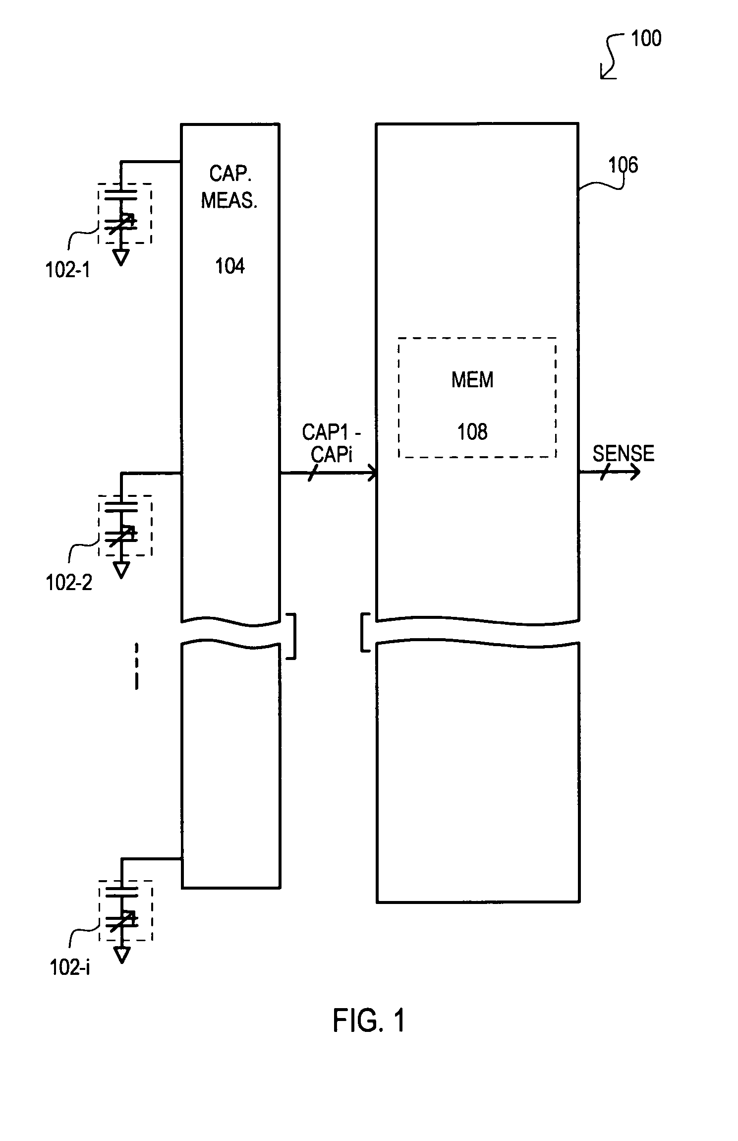
[0027]Referring now to FIG. 1, a system is shown in a block schematic diagram and designated by the general reference character 100. A capacitive sense system 100 can have inputs connected to a number of capacitive sensors 102-1 to 102-i. Each capacitive sensor (102-1 to 102-i) can have a capacitance that can vary depending upon mode of operation. More particularly, each capacitive sensor (102-1 to 102-i) can have a baseline capacitance that exists absent an input event. A baseline capacitance can be essentially constant, but can vary between capacitive sensors (102-1 to 102-i). In a run-time mode, each capacitive sensor (102-1 to 102-i) can be subject to an input event that can vary a resulting capacitance. As but one example, each capacitive sensor (102-1 to 102-i) can have a run-time capacitance that will drop in the event an object, such as a finger, is in close proximity to the sensor.

[0028]A system 100 can include a capacitance sensing section 104 and computation section 106....

second embodiment

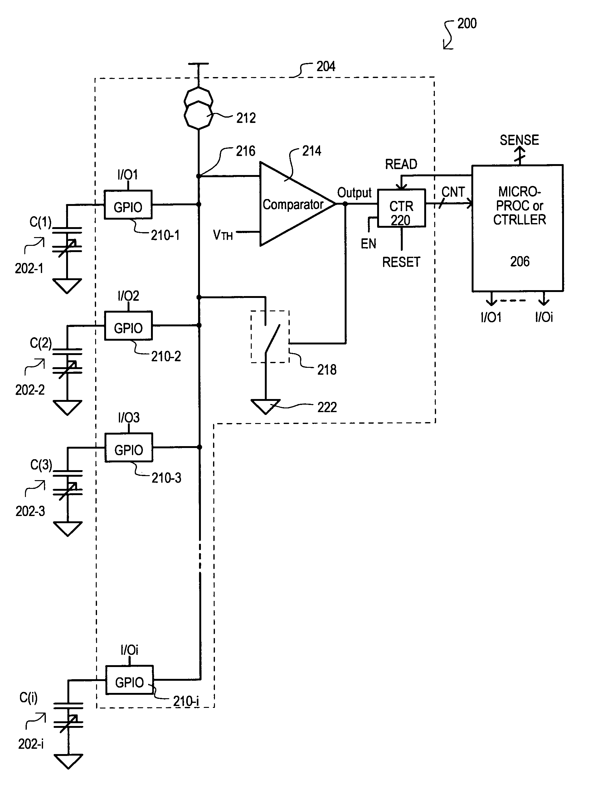
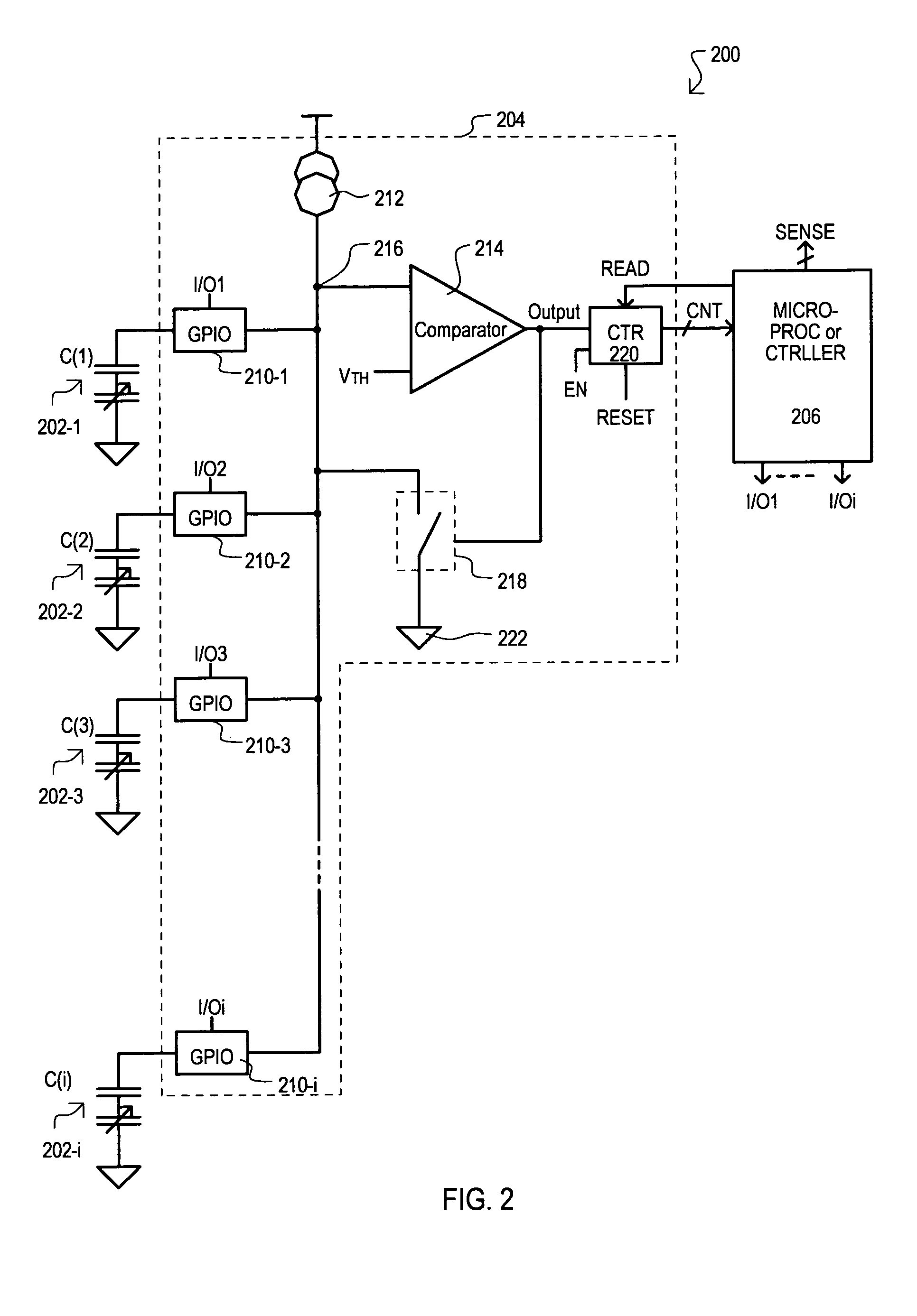
[0037]Referring now to FIG. 2, a system is shown in a block schematic diagram and designated by the general reference character 200. A system 200 can include some of the same general sections as FIG. 1, thus like sections are referred to by the same reference character, but with the first digit being a “2” instead of a “1”.

[0038]In the embodiment of FIG. 2, a sensing section 204 can include a number of general purpose input / output (GPIO) cells 210-1 to 210-i, a current source 212, a comparator 214, a reset switch 218, and a counter 220. Each capacitive sensor (202-1 to 202-i) can be tied to a corresponding GPIO cell (210-1 to 210-i). Individual GPIO cells (210-1 to 210-i) can be connected to a common bus 216 in a multiplexer type fashion. GPIO cells (210-1 to 210-i) can each be controlled by corresponding I / O signals I / O0 to I / Oi.

[0039]Current source 212 can be connected to a common bus 216 and provide a current. Such a current can be constant current when making capacitance measur...


PUM


Abstract

Disclosed is method for compensating for variation in the capacitance between multiple capacitive sensors. Prior to sensing operations, baseline capacitance values can be acquired for all sensors. A correction factor can be calculated based on such baseline values. During sensing operations (run-time), variations in capacitance from baseline values can be modified by appropriate correction factors. Sensitivity between sensors can thus be made more uniform.

Description

[0001]This application claims the benefit of U.S. provisional patent application Ser. No. 60 / 667,654, filed Apr. 1, 2005.TECHNICAL FIELD[0002]The present invention relates generally to electronic circuits, and more particularly to circuits related to capacitive sensors, including capacitive switches.BACKGROUND OF THE INVENTION[0003]Capacitive switches may be used as a replacement for mechanical switches in applications requiring an on / off action. A conventional capacitor switch can calibrate a single sensor, and apply filtering to try and eliminate changes on a time based algorithm. A typical conventional switch can use a single sensor, which can make the circuit susceptible to invalid readings due to movement of other capacitive bodies near the single sensor. In many applications, a conventional capacitance switch can “trip” when an object comes in close proximity.[0004]A conventional capacitive switch will now be described with reference to FIG. 6. A conventional capacitive switch...

Claims


Application Information

Patent Timeline
Patent Type & Authority Patents(United States)
IPC IPC(8): G01R27/26G06K9/00
CPCG06K9/0002G01R27/2605G01R35/00G06V40/1306
Inventor SEGUINE, DENNIS
Owner MONTEREY RES LLC
Why Eureka
Try Eureka