Self-tightening cover for pump

a self-tightening and pump technology, applied in the field of pumps, can solve the problems of frequent maintenance of valves, inability to stand the erosive environment of the pump chamber for an extended period, and the retaining cover is subject to inadvertent loosening, so as to improve safety.

Active Publication Date: 2009-03-24
GD ENERGY PROD LLC
View PDF20 Cites 67 Cited by
  • Summary
  • Abstract
  • Description
  • Claims
  • Application Information

AI Technical Summary

Benefits of technology

[0005]Among the several objects and features of the present invention may be noted the provision of a retaining system for securing a closure within a bore of a pump housing; the provision of such a system which enhances safety; the provision of such a system which self-tightens; the provision of such a system which is compatible with existing pump equipment; the provision of such a system which is reliable; and the provision of such a system which is economical.

Problems solved by technology

These valves require frequent maintenance.
Components of the valves are formed of a material which forms an effective seal, such as polyurethane, but which is incapable of withstanding the erosive environment of the pump chamber for an extended duration.
Unfortunately, the retaining cover is subject to inadvertently loosen.
The pump experiences substantial vibration during operation at high power settings such that the retaining cover can overcome its initially applied torque and begin to “back out”, or rotate in the access port in a loosening direction.
Should the retaining cover continue to loosen, the closure and a quantity of high pressure fluid would be ejected from the pump housing and potentially cause damage or injury.
That degrades efficiency and can necessitate the expense of a back-up pump for continuing a pumping operation while the primary pump is shut down.

Method used


Image

  • Self-tightening cover for pump
  • Self-tightening cover for pump
  • Self-tightening cover for pump

Examples


Embodiment Construction

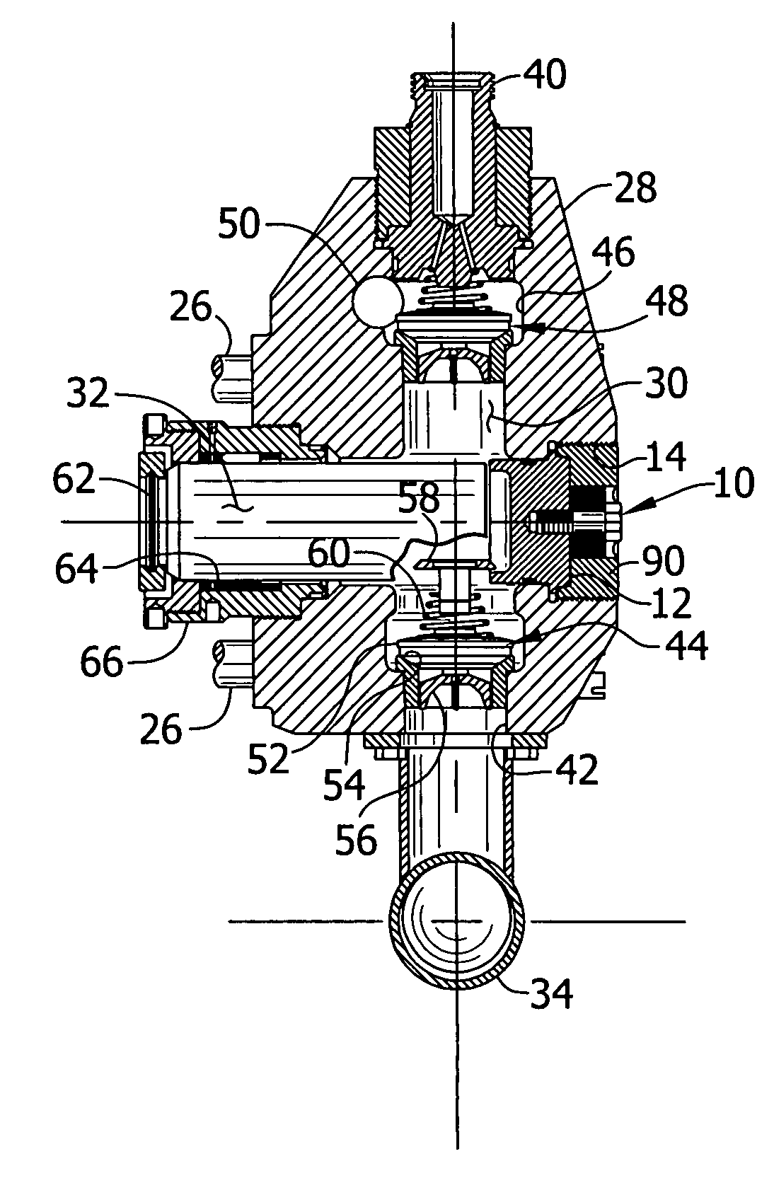
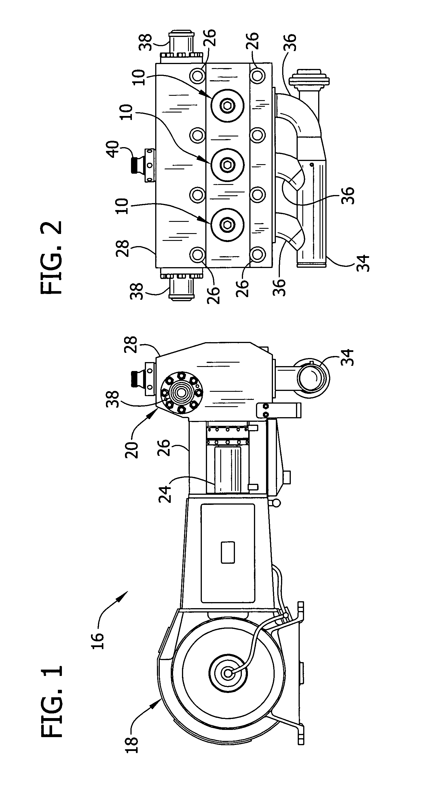
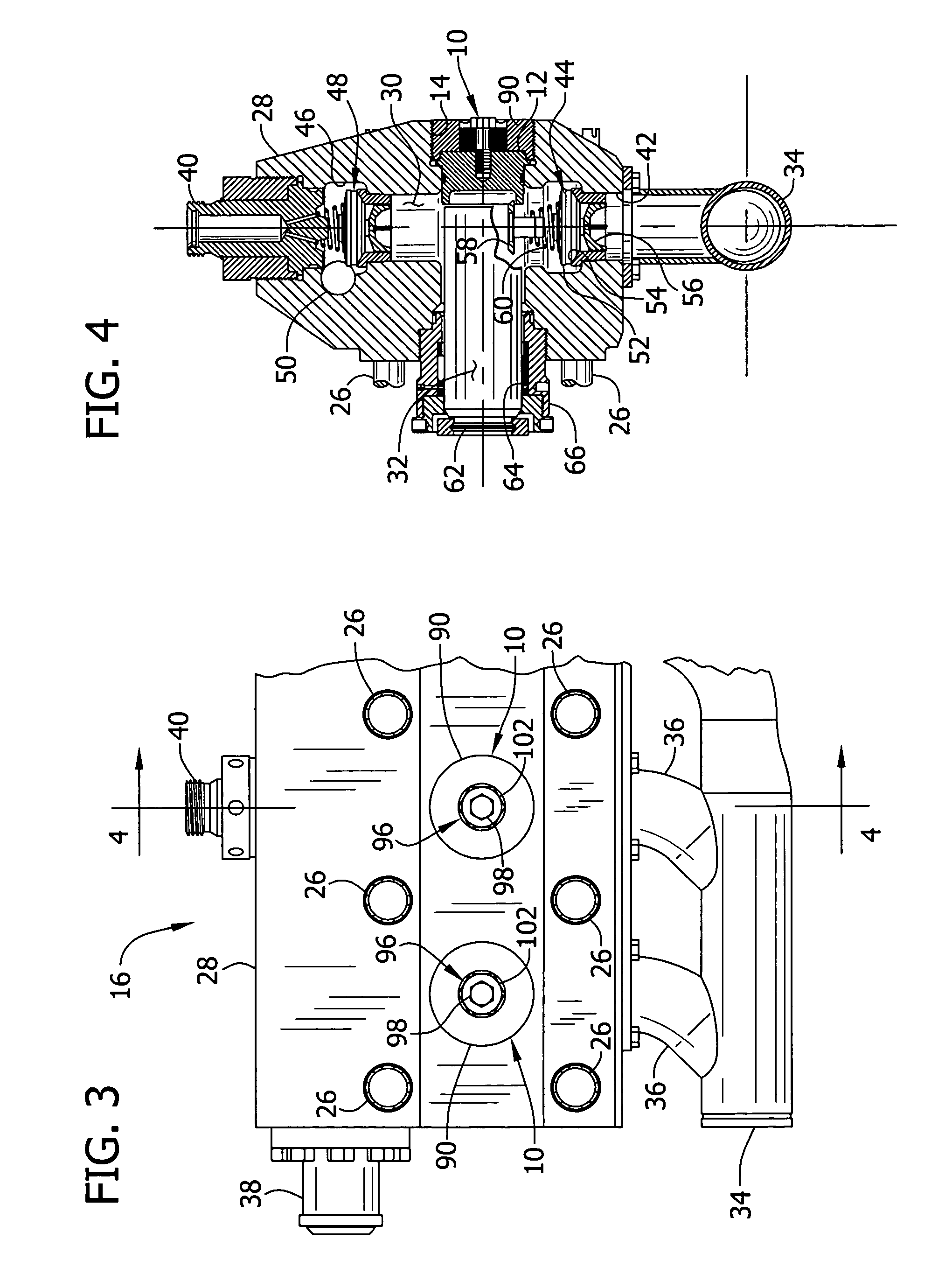
[0018]Referring now to the drawings and in particular to FIGS. 1-4, a self-tightening retaining system according to the present invention is indicated in its entirety at 10. The retaining system 10 secures a closure 12 within a bore 14 to close the bore. The system is particularly adapted for holding a plug member in a maintenance access bore of a high pressure reciprocating pump 16. The present description will primarily relate to that application. However, the retaining system may be used in a variety of applications to secure a body in a bore without departing from the scope of the present invention.

[0019]The pump 16 is adapted for operation at remote sites and may be placed on a vehicle such as a truck for transportation. The pump includes a first portion known as a “power end,” designated generally at 18 (FIG. 1), and a second portion known as a “fluid end,” designated generally at 20. The power end 18 includes a gearbox and housing for a crankshaft or eccentric (not shown) for...


PUM

PropertyMeasurementUnit
pressuresaaaaaaaaaa
sizeaaaaaaaaaa
polygonal shapeaaaaaaaaaa

Abstract

A self-tightening retaining system for securing a closure in position closing an access port of a pump housing. The system includes a retaining cover for obstructing removal of the closure from a bore of the access port. The cover has external threads interengageable with screw threads of the bore. A locking device is configured for being secured to the cover such that the locking device rotates together with the cover. The locking device has a fastener receivable in a hole of the closure and has external threads interengageable with threads of the hole. The threads of the cover and the threads of the fastener are spiraled in opposite directions such that when the cover rotates in a loosening direction, the fastener becomes tightened in the hole of the closure thereby stopping the rotation.

Description

BACKGROUND OF THE INVENTION[0001]This invention relates generally to pumps, and in particular to a self-tightening retaining system for holding a cover in position closing an access port of a pump housing.[0002]High pressure pumps are widely used in the petroleum industry for a variety of field operations relating to oil and gas wells. Such pumps deliver a fluid or slurry, which may carry solid particles (e.g., a sand proppant), at pressures up to 20,000 psi. A common type is a positive displacement pump having one or more plungers reciprocally movable in a corresponding pump chamber. Each chamber has an intake port for receiving fluid, a discharge port for exhaust, and a one-way flow valve in each port for preventing reverse flow. These valves require frequent maintenance. Components of the valves are formed of a material which forms an effective seal, such as polyurethane, but which is incapable of withstanding the erosive environment of the pump chamber for an extended duration. ...

Claims


Application Information

Patent Timeline
Patent Type & Authority Patents(United States)
IPC IPC(8): F01B11/02F04B11/00F04B39/00F16J10/00F04B23/04F04B41/06F04B53/16F16B39/16F16L55/115
CPCF04B53/007F04B53/16Y10T29/49256
Inventor JENSEN, ERNEST J.MCLAIN, ANTHONY W.
Owner GD ENERGY PROD LLC
Why Eureka
Try Eureka