

Drill bit dresser
- Summary
- Abstract
- Description
- Claims
- Application Information
AI Technical Summary
Benefits of technology
Problems solved by technology
Method used
Image

Examples
Embodiment Construction
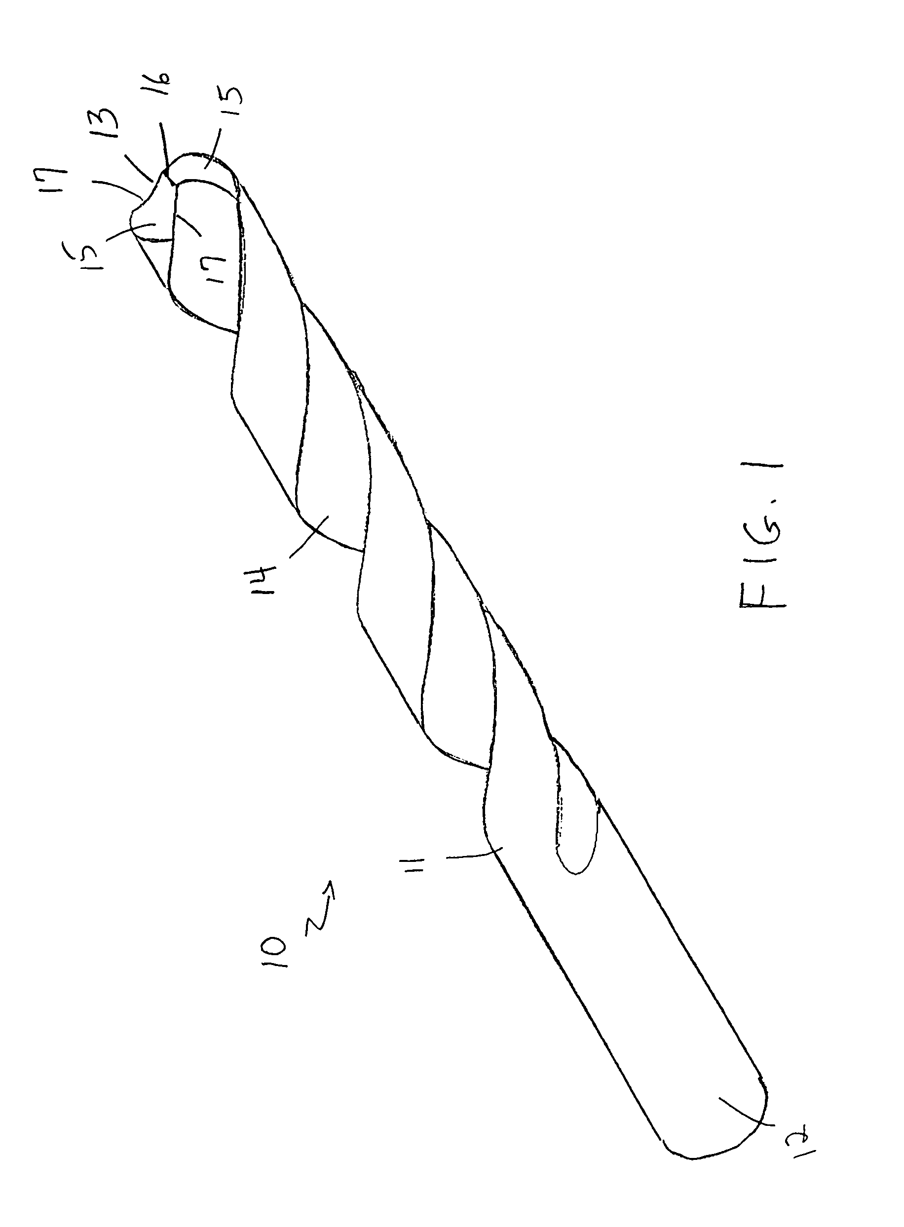
[0021]Referring to the drawings in detail wherein like elements are indicated by like numerals, there is shown in FIG. 1 a typical twist drill bit 10 having an elongated, generally cylindrical body 11 with a rear shank end 12, adapted to being held in a chuck, and a pointed leading end 13. The drill bit body 11 has two helical channels 14 extending substantially the length of the body and each terminating in a drill bit face 15, and angling up to a point 16 forming the drill bit leading end 13. The drill bit faces 15 provide the drill bit cutting edges 17.
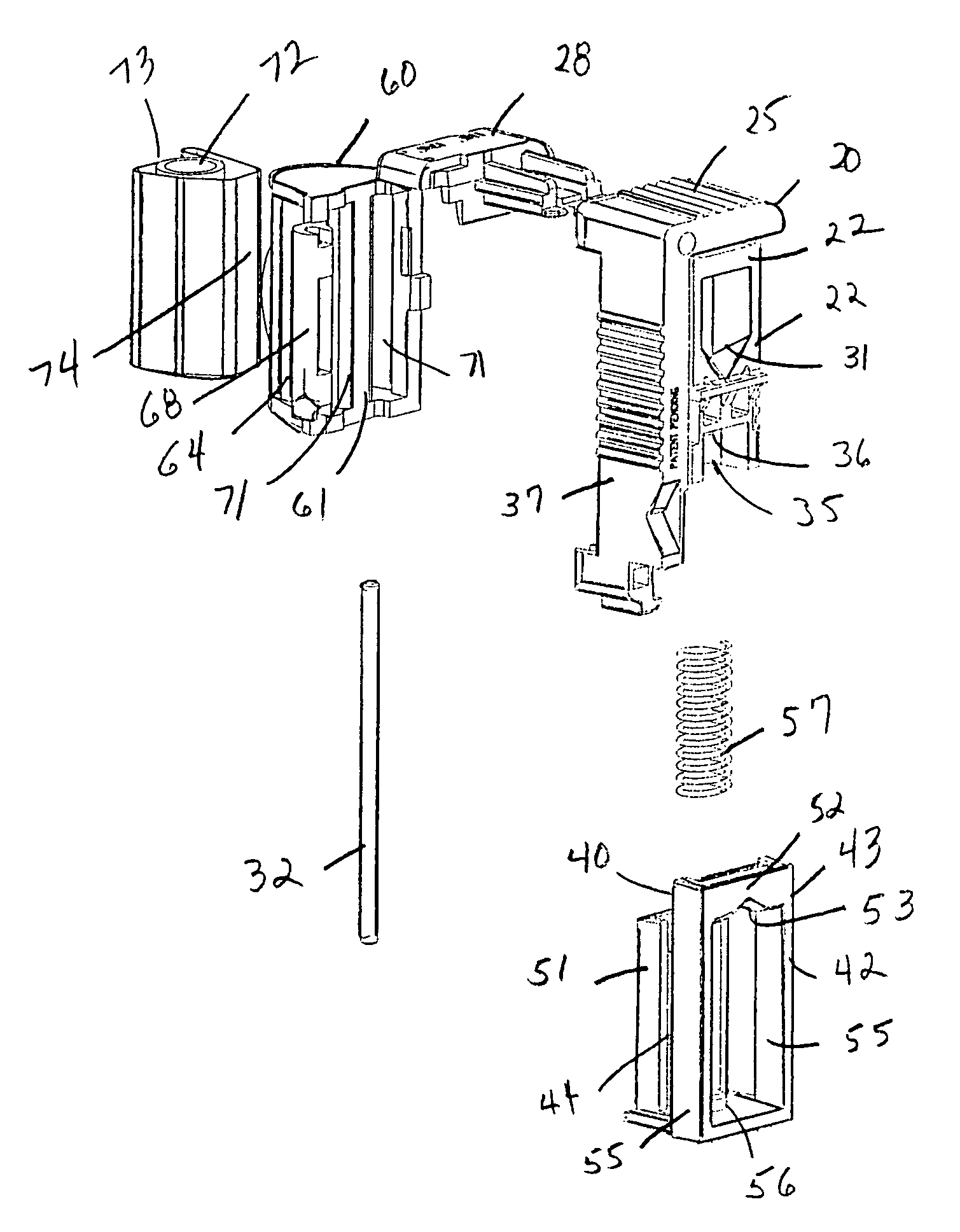
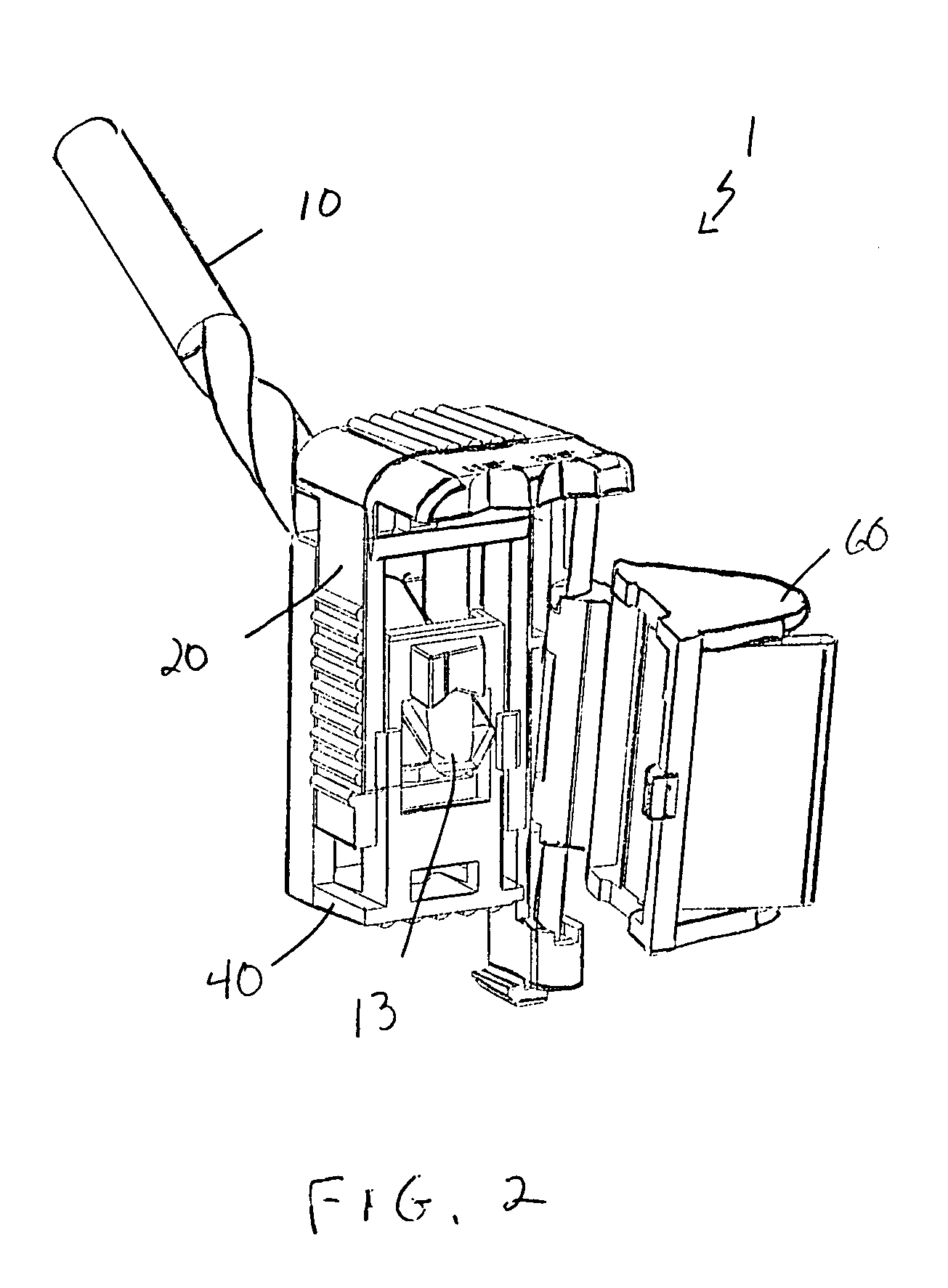
[0022]In accordance with the present invention, and as illustrated in FIGS. 2 through 9, the drill bit dresser 1 includes a dresser body 20, a holding clamp 40 slidably joined to the dresser body 20, and a sanding shoe 60 pivotally attached to the dresser body 20. A drill bit 10, leading end 13 first, is inserted into the dresser body 20 and held in a desired positioned by the holding clamp 40. The sanding shoe 60 is pivoted to the...
PUM
| Property | Measurement | Unit |
|---|---|---|
| Angle | aaaaa | aaaaa |
| Shape | aaaaa | aaaaa |
| Distance | aaaaa | aaaaa |
Abstract
Description
Claims
Application Information