Shirred casing

a casing and food technology, applied in the field of shirred food casings, can solve the problems of less adaptability to automatic stuffing process, limited shirring technique, and shirring of collagen casings

Active Publication Date: 2009-03-24
VISKOTEEPAK BELGIUM NV
View PDF63 Cites 17 Cited by
  • Summary
  • Abstract
  • Description
  • Claims
  • Application Information

AI Technical Summary

Problems solved by technology

Collagen casings, which are often edible and therefore are more delicate than skinless cellulose casings, are less adaptable to automatic stuffing processes.
Shirring techniques have generally been limited for fibrous casings of this type due to the effects of excessive compaction of casing within the shirred stick, which impedes soakability.
A significant limitation of the current technology is that casings shirred today using conventional methods do not permit long lengths of casing to be compacted within the shirred stick and still achieve adequate soaking with a desired shirred stick length and a desired shirred stick inner diameter.
The excessive density of casing packed into the stick often prevents sufficient wetting of the casing during soaking.
The result of the high overshirr of the shirring rolls required to pull the casing is that a high number of relatively short pleats are formed, including forming a large number of non-uniform or “nuisance” pleats that create stress on the casing due to irregular folding, impeding water absorption by blocking passageways for water penetration into the stick by capillary action, and retarding efficiently compacting long lengths of casing into the shirred stick without damage, since each pleat or fold adds corresponding nuisance pleats.
This is further impeded because as the casing absorbs water, the cellulose structure swells up, and the fibrous casing thickness often increases by 50% to 100% of its original thickness, further restricting passage of water into the interior of the shirred stick.
In addition to the problems noted above with respect to compaction, excessive abrasion and damage resulting in pinholing occurs when the shirring rolls and teeth have a much higher velocity than the velocity of the casing fed from the feedroll (i.e.: high overshirr).
In the case of high overshirrs, abrasions on the surface of the casing are a significant problem aggravated by the excessive differential velocity of shirring tooth verses incoming casing.
Using current technology, if overshirr is excessive with a given number of teeth, creating excessively high shirring tooth velocities relative to the feedroll velocity, the only method of operating with reduced overshirrs and still obtain a desired pleat pitch is to add more shirring teeth to the shirring roll, which will help to shorten the pleat length for a given velocity to conform to the ideal geometric requirement, but has limited pulling power since shorter pleats which are harder to pull typically require higher overshirrs just to grab the casing.
Thus, although adding teeth results in reducing overshirr requirements, serving to shorten the pleat pitch as geometrically required when shirring mandrel diameter increases relative to the casing inflated diameter, this action also greatly reduces the pulling power of the shirring head.
With respect to Kollross's vacuum assist shirring, the very slow speeds at which the shirring machine overall operates, creating a very low productivity coupled with the enormous power requirements for vacuum shirring result in a shirring method that is not commercially viable.

Method used


Image

  • Shirred casing
  • Shirred casing
  • Shirred casing

Examples


example 1

Standard KüKo Axial Shirring Head

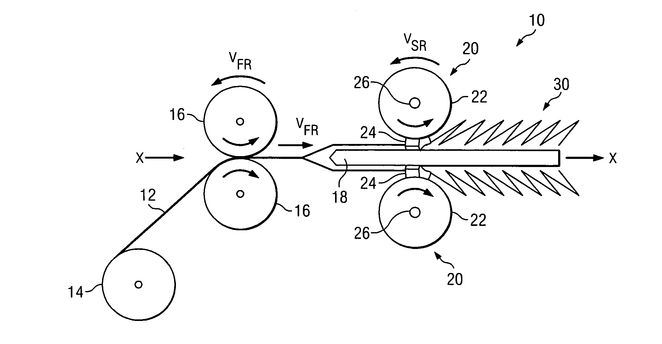
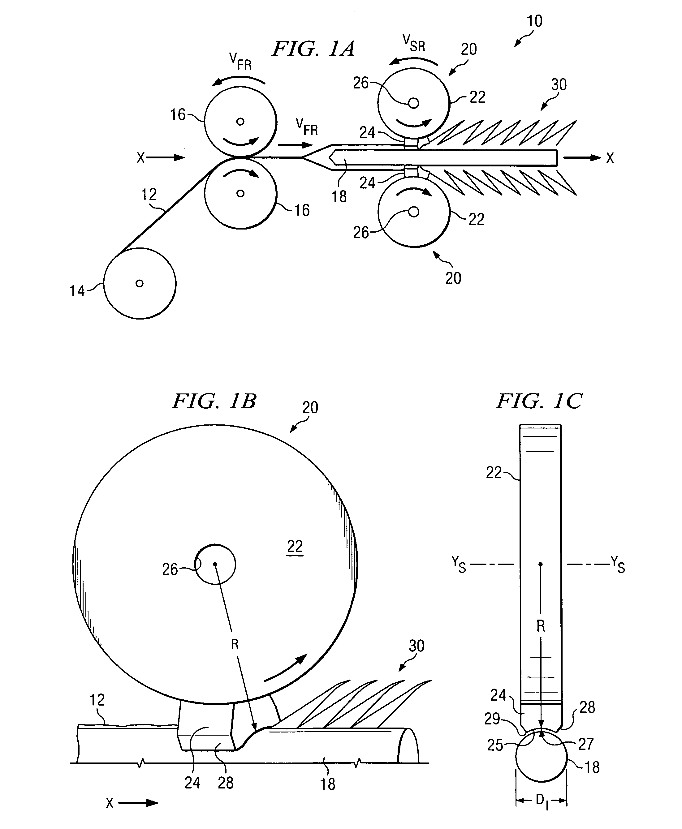
[0052]The first test was conducted using an axial shirring head as described above with respect to FIGS. 2A-2B. The shirring machine was the Küko 5 distributed by Küko Maschinenbau, (no longer commercially active), with the above-stated 35.5 mm mandrel with a Teflon coating. The casing was pre-moisturized to an average of 16% water to casing by weight, and of the type requiring soaking after shirring and prior to stuffing.

[0053]The casing was fed into the shirring machine at a velocity of VFR=145 m / min, and the shirring roll velocity VSR=346 m / min, for an overshirr of 238.6%. The clearances between the shirring teeth and the mandrel were 2.5 mm as measured with the shirring teeth proximate to the mandrel. Standard clearances using the existing shirring methods are about 2.5 mm to 5 mm to prevent the casing from bunching or becoming jammed in the shirring machine at the shirring head. This overshirr can also be determined by measuring the pleat pitch ...

example 2

Improved Shirring Method and Casing

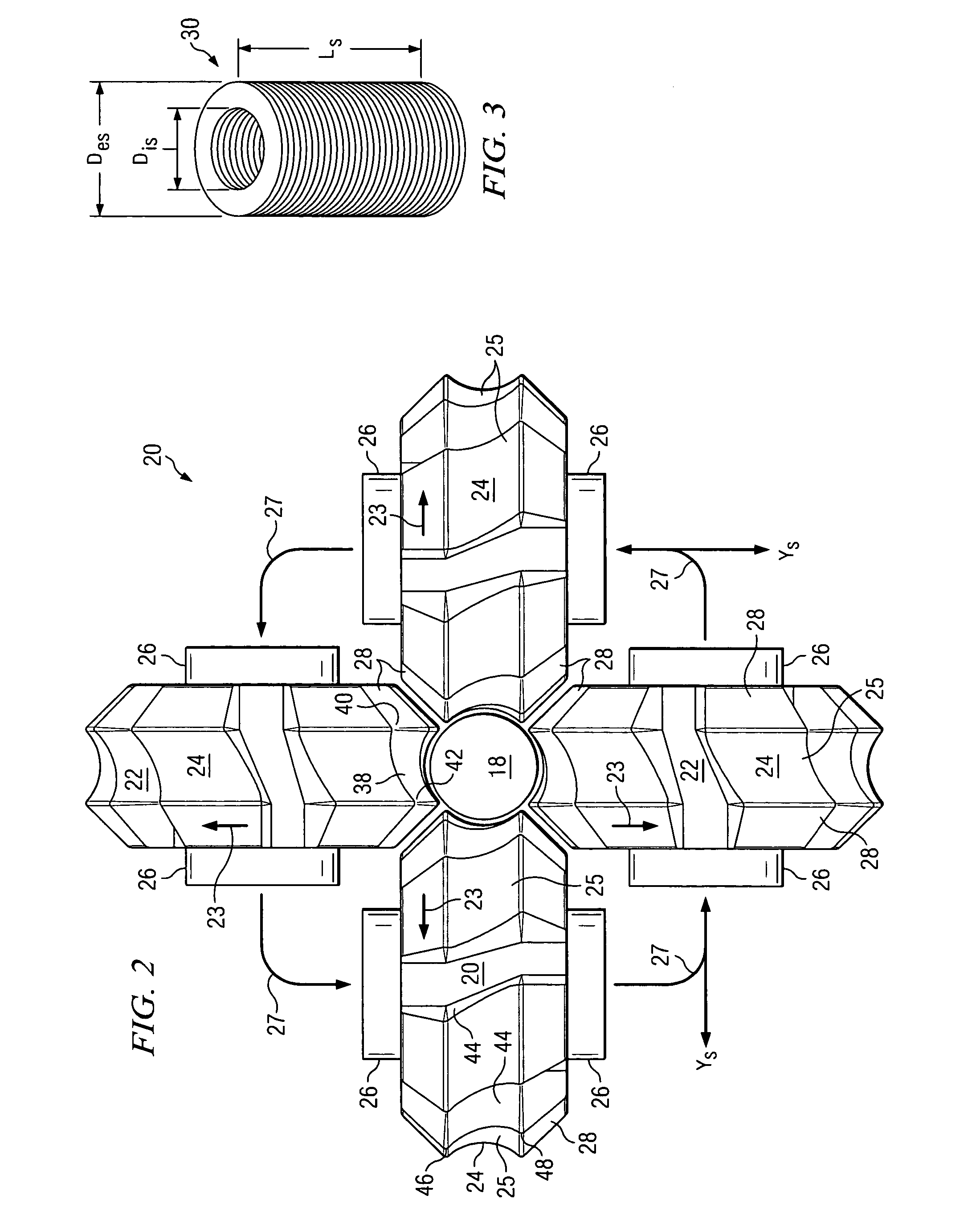
[0055]Surprisingly, it has been discovered that by using the continuous spiral shirring head 20 illustrated by FIGS. 2A-2C above, and reducing the clearance between the shirring teeth 24 and the mandrel 18, shirred sticks 30 having pleat pitches far larger than the theoretical pleat pitch described above may be obtained. The most significant result of the longer pleat pitch is the ability to obtain shirred sticks 30 with outside diameter more than 15% greater than the casing inflated diameter on mandrels that have a diameter of at least 70% to 80%, and even as great as 90% of the casing inflated diameter. It is advantageous for the outside diameter of the shirred stick to be large, to achieve a volume in the shirred stick in which to pack casing, as discussed below, to be able to properly moisturize a casing that is designed to be soaked after shirring. Accordingly, with larger stick outer diameters more casing length can be metered into the shirre...

example 3

Improved Shirring Method and Casing

[0062]A third test was performed with a casing with an inflated diameter DI of 46.2 mm. The values of the relevant variables for this test were:[0063]DM=37.5 mm[0064]DI=46.2 mm[0065]DM / DI=81.2%

[0066]Again, reducing the overshirr to 129% the resulting shirred outer diameter Des was 54 mm, which was greater than the prior art at 51.5 mm. With example 3 the ratio of mandrel diameter to inflated casing diameter was 81.5%. The theoretical pleat pitch for this casing, according to formula (3), was 37.9 mm. After shirring, the shirred stick had a pleat pitch of 65 mm, which was 172% of the theoretical pleat pitch. Also, the DFW was 72.5 mm, which translates to a pleat pitch-to-dry flat width ratio of over 90%. More significantly, the shirred stick also had a ratio of shirred stick outside diameter-to-inflated casing diameter of 117% based on the DI of 46.2 mm.

[0067]The casing was shirred with a moisture content of approximately 18% by weight, so removing ...


PUM


Abstract

A shirred fibrous food casing defines a shirred stick formed from a tubular fibrous casing. The shirred stick includes an average outside diameter at least 120% of the average inflated diameter of the deshirred casing. Additionally, the shirred stick includes an average inside diameter of at least 70% of the casing inflated diameter and a pleat pitch defined as the distance between adjacent apexes of major pleats measured on the casing after the shirred stick is deshirred.

Description

TECHNICAL FIELD[0001]This disclosure relates to tubular food casings, and more particularly to an improved shirred food casing.BACKGROUND[0002]Artificial food casings, including plastic casings and cellulose casings, have been used for many years as containers in which food products are manufactured and stored. In commercial applications, the food casings are generally loaded either by hand or automatically into a food stuffing machine in order to stuff food products, such as sausage, meats, vegetables, or other food products, into the casings. In order to increase the length of casing that can be utilized at one time, casings have for years been compressed through ruffling or other compression techniques, into short, compact lengths, called shirred sticks or shirred strands.[0003]Casings can be natural or artificially manufactured. Artificial casings generally fall within one of four categories: skinless cellulose casings (small calibers, pure regenerated cellulose), collagen casin...

Claims


Application Information

Patent Timeline
Patent Type & Authority Patents(United States)
IPC IPC(8): A22C13/02
CPCA22C13/02
Inventor STALL, ALAN DAVIDSIMMERLY, DENNIS BRUCEWATTS, KEITH ARTHUR
Owner VISKOTEEPAK BELGIUM NV
Why Eureka
Try Eureka