
Magnetic resonance apparatus with a gradient coil unit with integrated passive shim devices

a gradient coil unit and magnetic resonance technology, applied in the direction of optical resonator shape and construction, using reradiation, instruments, etc., can solve the problems of easy error, pocket occupancy, and time-consuming methods, and achieve the effect of simple design and improved shim devices

Inactive Publication Date: 2009-03-24
SIEMENS HEALTHCARE GMBH
View PDF18 Cites 17 Cited by
  • Summary
  • Abstract
  • Description
  • Claims
  • Application Information

AI Technical Summary

Benefits of technology

[0005]An object of the present invention is to provide a magnetic resonance apparatus with an improved, simpler design of the shim devices.
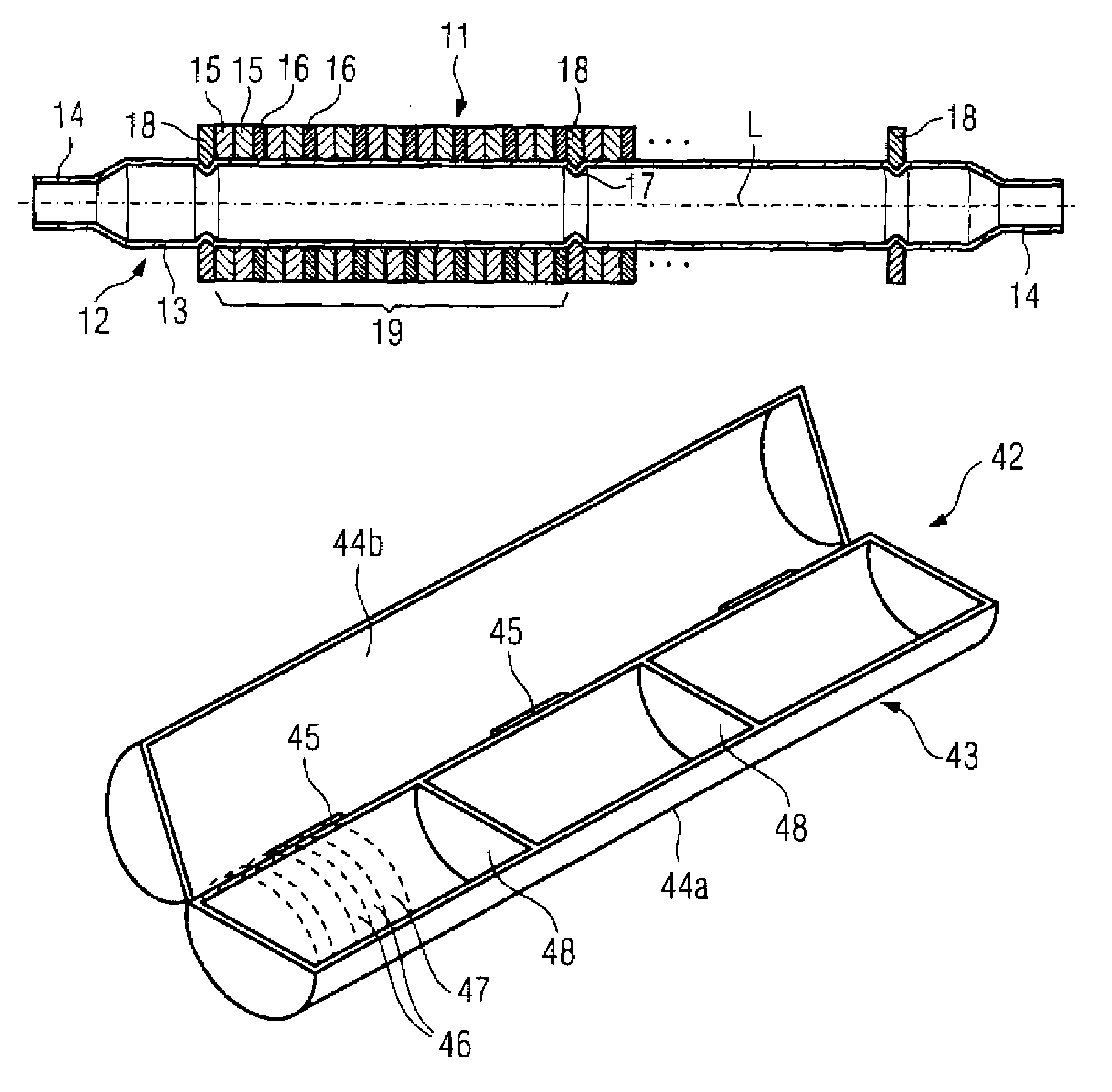
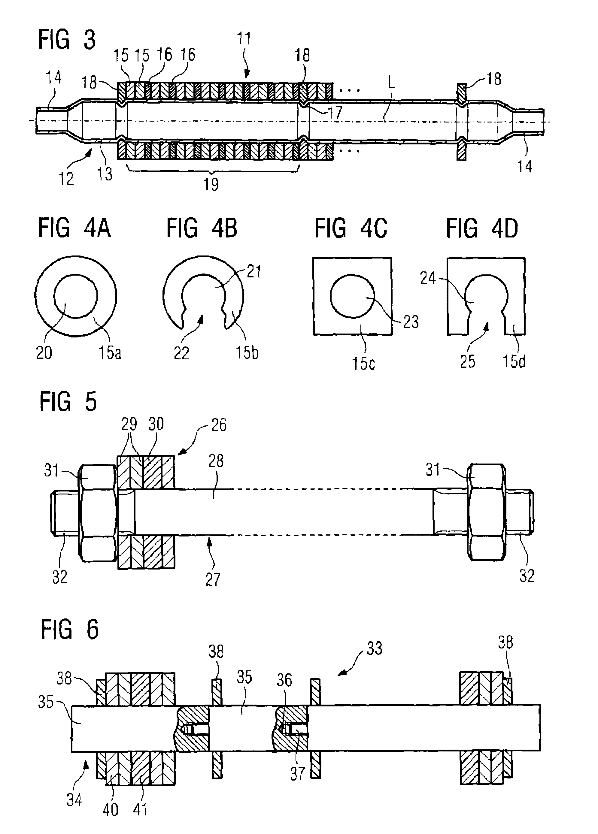
[0009]The rod-shaped or tube-shaped carrier can be formed in one piece, but it is also possible to form it from a number of carrier segments that can be detachably connected with one another by screw or plug connections, which enables a simple adaptation of the carrier length to the existing coil unit length. This means that, in this embodiment, the carrier can have standardized carrier segments depending on a given coil unit length.
[0011]As an alternative to the embodiment using the grooves together with inserted separator elements, it is possible to brace the entire metal and spacer element packet relative to the entire carrier length in order to be able to compensate the length tolerance depending on the bracing pressure.
[0013]The metal elements and, if applicable, spacer elements each can have a circular closed recess or a recess open to one side. Given a closed recess, which (depending on the cross-section of the carrier) can also be rectangular or oval, the metal and spacer elements are slid onto the carrier end. Given a recess open to one side, in addition to such sliding it is also possible to push or snap the elements onto the carrier from the side. This embodiment also allows a simple exchange of a metal element or spacer, such as when the entire design must be changed in a further iteration step to optimize the field homogeneity. It is then possible to pull off individual metal or spacer elements from the carrier orthogonal to the carrier longitudinal axis and to insert a new element.

Problems solved by technology

This method is very time-consuming and occupies approximately 2-3 days for a new installation.
Errors are easily possible since, as stated, the discs must be counted and inserted by hand.
A further disadvantage is that the occupancy of a pocket can be checked only by removing the entire disc packet, since the discs are not visible from the exterior of the pocket due to being arranged lying atop one another.

Method used


Image

  • Magnetic resonance apparatus with a gradient coil unit with integrated passive shim devices
  • Magnetic resonance apparatus with a gradient coil unit with integrated passive shim devices
  • Magnetic resonance apparatus with a gradient coil unit with integrated passive shim devices

Examples


Embodiment Construction

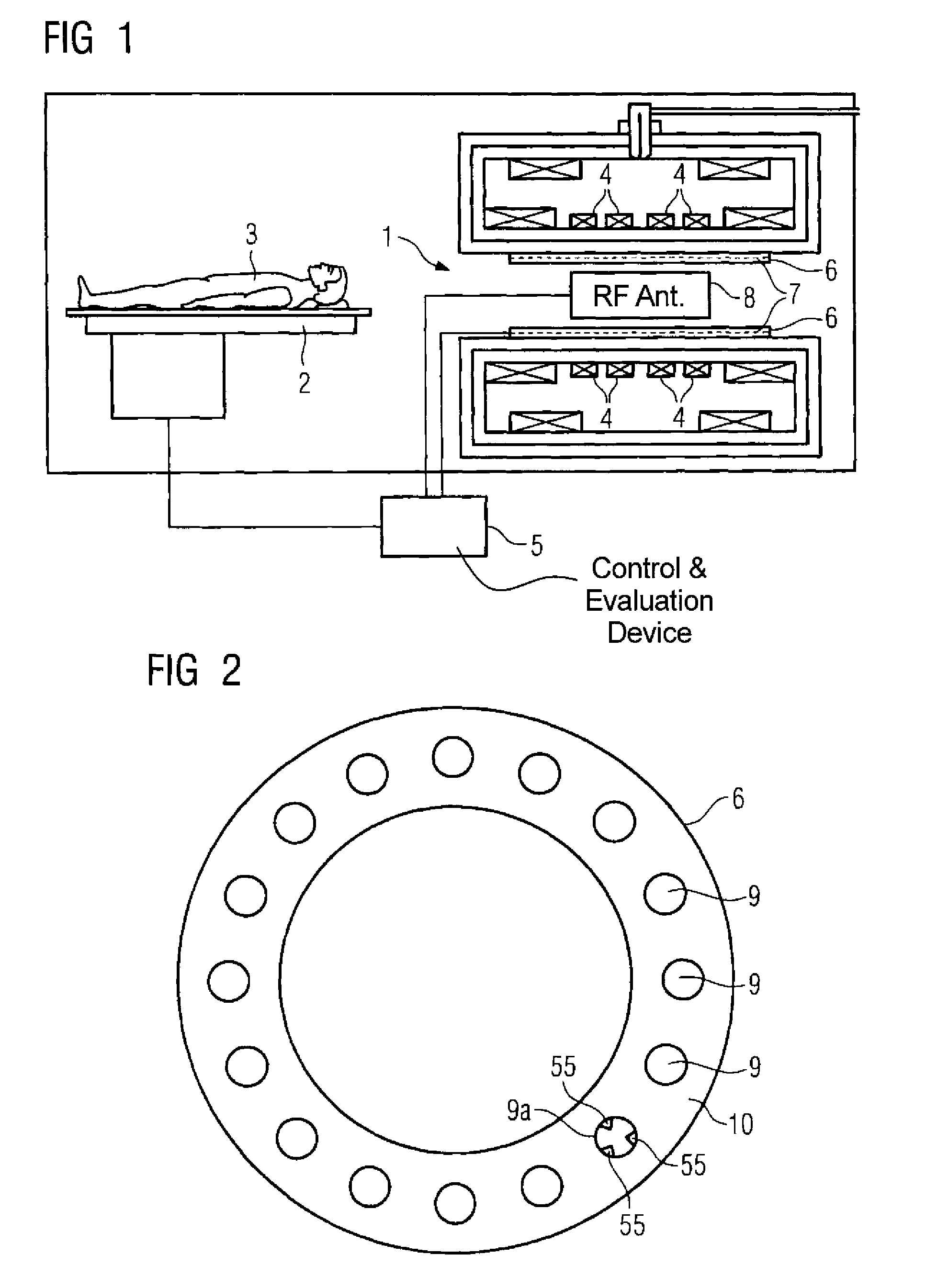
[0028]FIG. 1 shows an inventive magnetic resonance apparatus 1 in a known embodiment. An examination subject 3 (here a person) can be introduced into the examination region by means of a patient bed 2. The examination region (which corresponds to the examination volume) is occupied by a basic magnetic field generated by a basic field magnet 4. The basic magnetic field is temporally constant (static) and spatially as homogeneous as possible and exhibits a measurement field strength that is preferably 3 T or more. The basic field magnet 4 is usually fashioned as a superconductor. A control and evaluation device 5 controls the system operation and also represents the image reconstruction components.

[0029]The magnetic resonance apparatus also has a gradient coil unit 6 carrying gradient coils (now shown) that respectively generate orthogonal gradient fields in the examination region. The coils of the gradient coil unit 6 can be activated by the control and evaluation device 5 such that ...


PUM


Abstract

A magnetic resonance apparatus has a gradient coil unit with passive shim devices inserted into side receptacles in the molded body of the gradient coil unit. Each shim device has a carrier with a number of metal elements, the metal elements being mounted on the carrier in linear succession and being situated essentially orthogonally to the longitudinal axis of the carrier.

Description

BACKGROUND OF THE INVENTION[0001]1. Field of the Invention[0002]The present invention concerns a magnetic resonance apparatus of the type having a gradient coil with passive shim devices inserted into receptacles in the unit, each shim device being formed by a number of ferromagnetic metal elements.[0003]2. Description of the Prior Art[0004]To improve the homogeneity of the basic magnetic field within the measurement volume of a cylindrical magnetic resonance apparatus, shim devices (formed by disc-shaped, laminar metal elements, in particular iron discs) are used that are inserted into separate receptacles in the form of pockets molded into the gradient coil unit and arranged around the measurement volume in a cylindrical wall. This metal or iron arrangement is known as a passive shim. The shim arrangement in total can have several hundred metal discs. The locations of the discs and their number are normally determined via an iterative calculation method for which the measurement f...

Claims


Application Information

Patent Timeline
Patent Type & Authority Patents(United States)
IPC IPC(8): G01V3/00
CPCG01R33/3856G01R33/3873
Inventor DIETZ, PETERSCHUSTER, JOHANNSTOCKER, STEFAN
Owner SIEMENS HEALTHCARE GMBH
Learn More