
System and method for multi-target fluid concentration detection and mapping

a multi-target, fluid concentration technology, applied in the field of remote detection of fluid leakage, can solve the problems of ambiguity or difficulty in detecting the on-line return, low off-line and on-line returns, and difficulty in detecting gas and oil pipeline failures

Active Publication Date: 2009-03-24
HARRIS CORP
View PDF9 Cites 25 Cited by
  • Summary
  • Abstract
  • Description
  • Claims
  • Application Information

AI Technical Summary

Benefits of technology

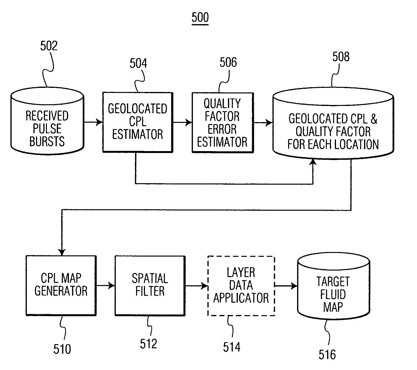
[0010]The present invention is also embodied in a system for obtaining a target fluid map of a survey area using a DIAL system that transmits a plurality of pulse bursts toward the survey area. Each transmitted pulse burst includes an off-line pulse and at least one on-line pulse. The system includes an input terminal for receiving a plurality of pulse bursts from the survey area, where each pulse burst is associated with a measurement point. The system also includes...

Problems solved by technology

It is difficult to detect failures of gas and oil pipelines, because the gas or oil pipeline is typically buried beneath ground level.
This low signal-to-noise ratio (SNR), when the target fluid is present in the survey area, results in ambiguities or difficulties in detecting the on-line returns.
Low surface cover reflectivity results in low off-line and on-line returns whereas high surface cover reflectivity results in high returns.
When the returned signal is low relative to noise, electrical noise may dominate and cause a low SNR and large CPL variance, but the opposite is also true.
However, it may be difficult to correct for reflectivity variations due to the type of surface cover in many situations.
If the surface cover reflectivity variations are not properly corrected, significant errors in CPL estimates of the target fluid may result, leading to false identification of target fluid plumes (or lack of plumes).

Method used


Image

  • System and method for multi-target fluid concentration detection and mapping
  • System and method for multi-target fluid concentration detection and mapping
  • System and method for multi-target fluid concentration detection and mapping

Examples


Embodiment Construction

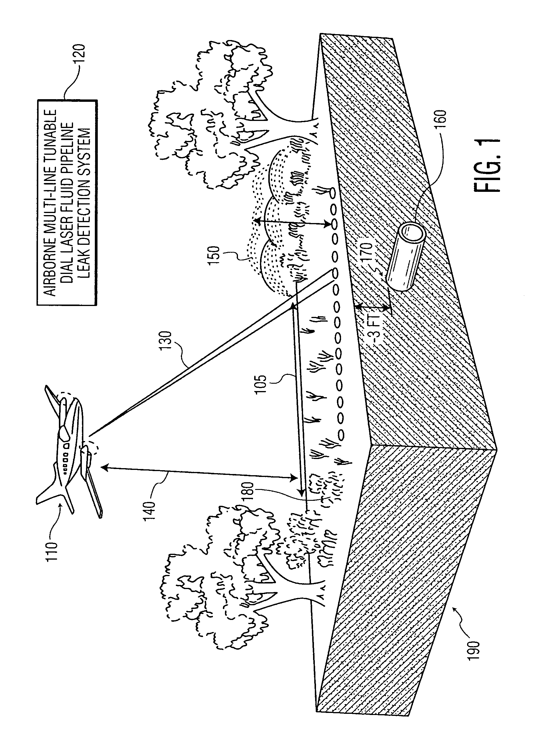
[0028]The present invention described herein addresses the concentration detection of measured target fluids, for example trace gases associated with oil and gas leakages from pipelines. This invention relates to an oil and gas pipeline leak detection system and method of detecting gas concentration in the atmosphere and more particularly, but not by way of limitation, to mapping pipeline leak concentration over a survey area based upon differential absorption lidar (DIAL) sensing techniques operating in a mid-infrared spectral range.

[0029]In general, many fluids may be detected or explored, such as gas, volatile oil, light crude oil, heavy crude oil, hazardous gases, hazardous liquids, or chemical and biological agents. Gas concentrations, for example, may be mapped over an area and the maps may be analyzed for concentration anomalies. These gas anomalies may be interpreted to determine underground pipeline leaks.

[0030]As used herein, the term “target fluids” indicates fluids that ...


PUM


Abstract

Methods and systems for obtaining a target fluid map of a survey area using a differential absorption LIDAR (DIAL) system are provided. Pulse bursts are transmitted toward the survey area, where each pulse burst includes an off-line pulse and at least one on-line pulse. Pulse bursts, each being associated with a measurement point, are received from the survey area. A concentration path length (CPL) corresponding to a respective on-line pulse, a spatial location associated with the CPL, and an error associated with the CPL are determined for each measurement point. The CPL for each measurement point is arranged within the survey area to form the target fluid map.

Description

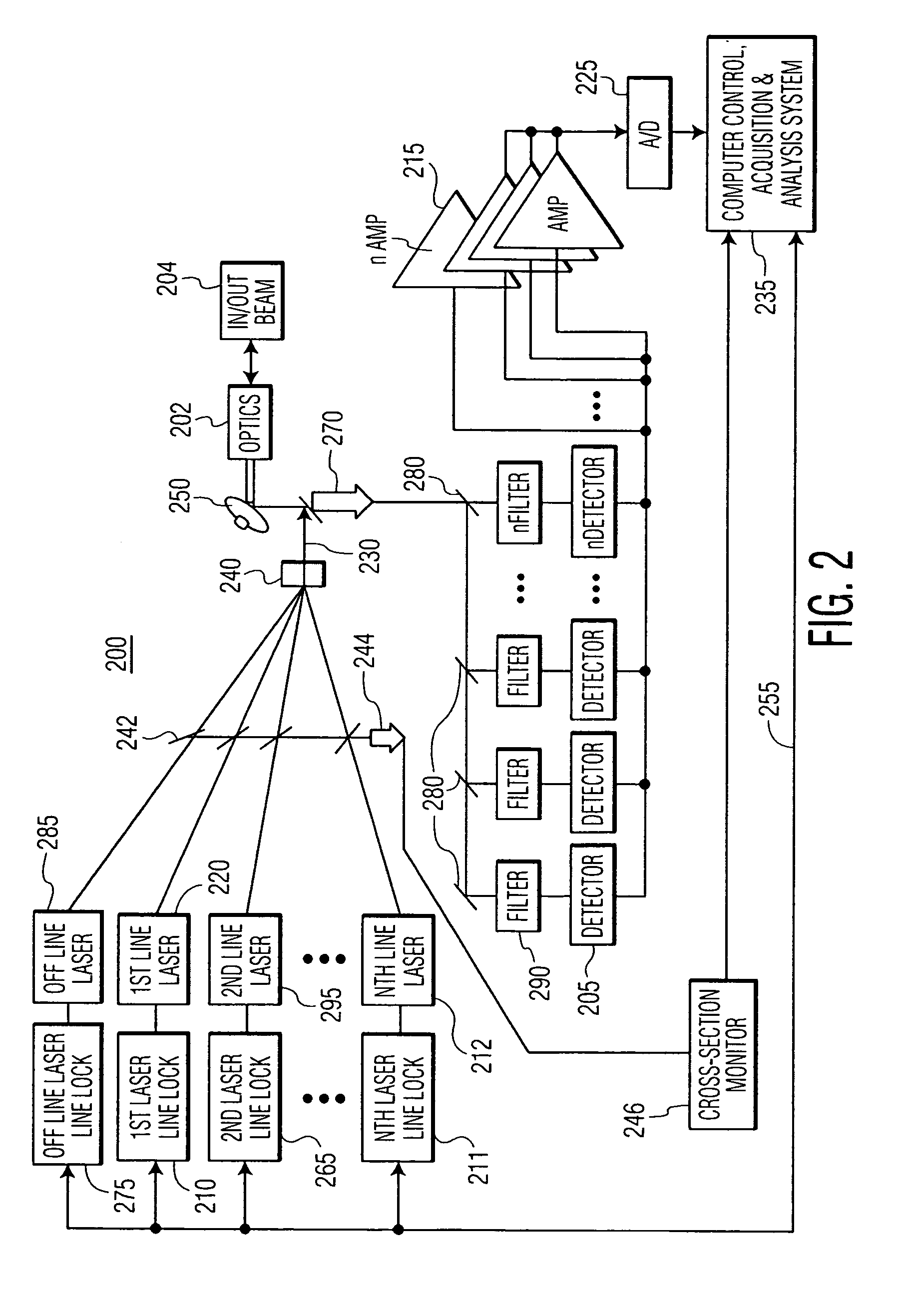
FIELD OF THE INVENTION[0001]The present invention relates to remotely detecting fluid leaks in general and, specifically, to systems and methods for measuring and mapping fluid concentrations.BACKGROUND OF THE INVENTION[0002]Detection of fluid leaks, such as natural gas leaks from pipelines, is well known in the art. It is difficult to detect failures of gas and oil pipelines, because the gas or oil pipeline is typically buried beneath ground level. When failures do occur, they are manifest by the leakage of the pipeline contents, where the leaking material produces a characteristic trace or signal which may be measured. Because fluids can escape from a pipeline and travel through subterranean earth to the earth's surface and then into the atmosphere, the atmosphere can be monitored for the trace fluids.[0003]Differential absorption LIDAR (DIAL) systems may be used to remotely measure the chemical composition of fluids in the atmosphere. DIAL systems may be provided on an airborne o...

Claims


Application Information

Patent Timeline
IPC IPC(8): G01N21/00
CPCG01N21/3504G01N21/39G01N2021/1797G01N2021/3513G01N2021/393G01N2021/394G01N2021/395
Inventor LINES, RAYMOND TODDLOPEZ, NORMAN A.LIPPERT, JOSEPH L.MURDOCK, DARRYL GUYLENZ, DAWNSTOOGENKE, MICHAELSEVERSKI, MATTHEW C.KALAYEH, HOOSHMAND M.
Owner HARRIS CORP
Learn More