

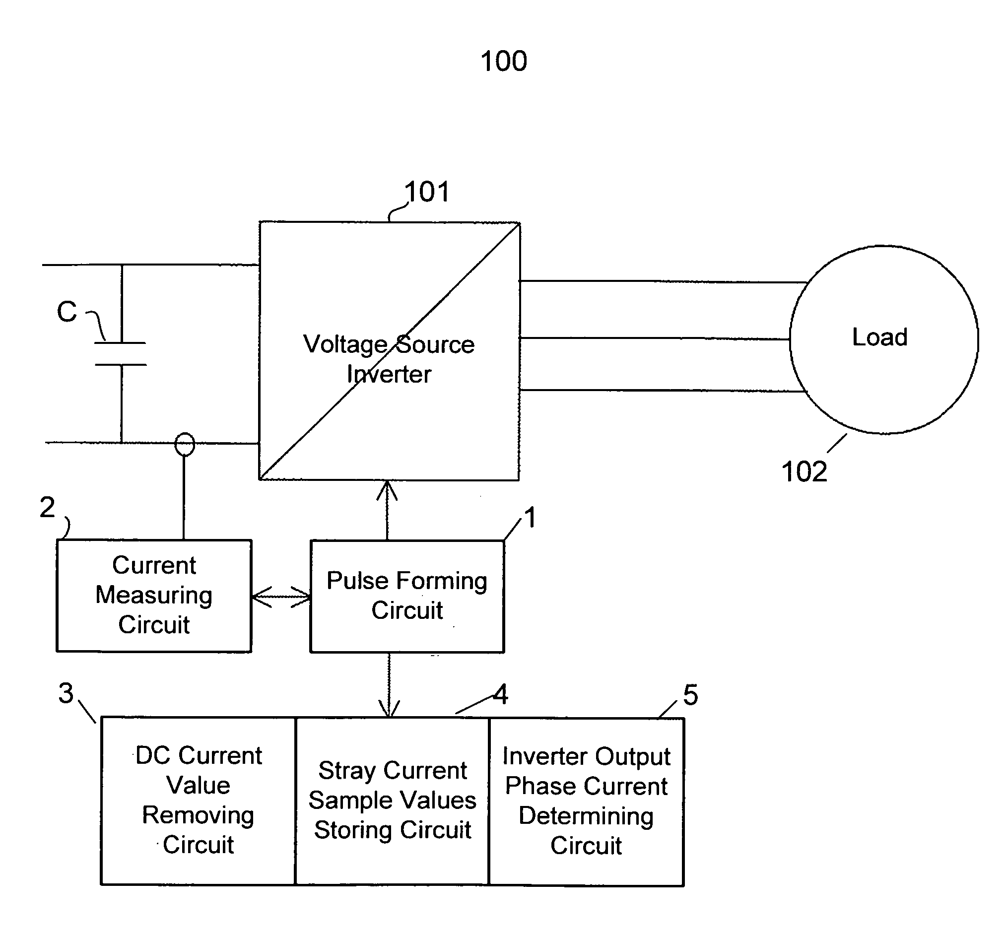
Method and arrangement for measuring output phase currents of a voltage source inverter under a load
a voltage source inverter and output phase current technology, which is applied in the direction of power supply testing, instruments, process and machine control, etc., can solve the problems of large capacitance, error in measurement, and the magnitude of stray currents at their highest, so as to achieve the effect of determining the load current more accurately
- Summary
- Abstract
- Description
- Claims
- Application Information
AI Technical Summary
Benefits of technology
Problems solved by technology
Method used
Image

Examples
Embodiment Construction
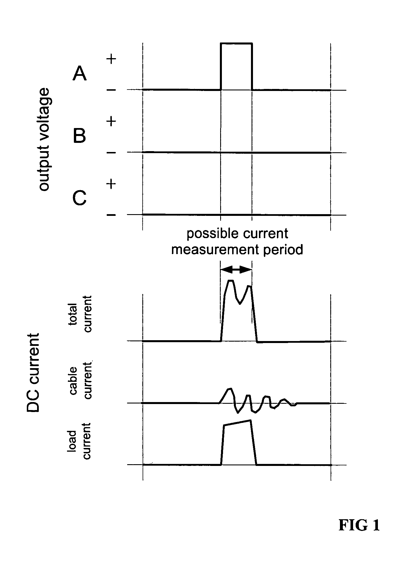
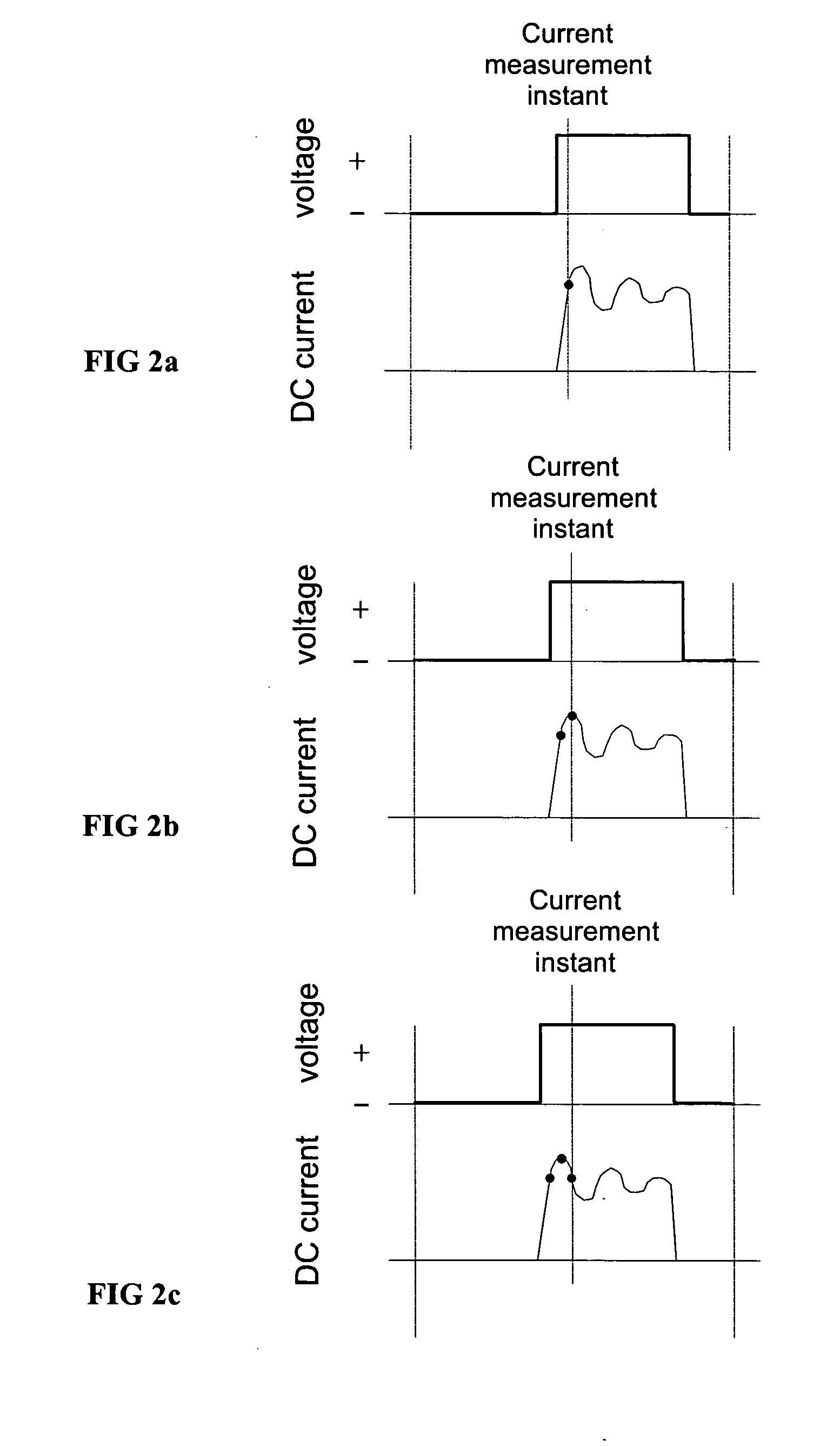
[0021]In the method of the invention, the first steps are taken during commissioning of an inverter in question i.e. before actual use of the inverter. When both the inverter and a load, which usually is a motor, are properly installed and connected via cabling, a drive is put to use by starting an identification procedure. Identification procedures are commonly used before the first start where a frequency converter executes a procedure where it measures different values, generates parameters for the control, etc. As a part of this routine, according to the present invention, a voltage source inverter forms consecutive voltage pulses to the load. These voltage pulses are preferably identical to each other and generated with the same phase. After each pulse, a current sample is taken. The measurement instant of the current measurement is changed in respect to each voltage pulse, and only one current sample is taken during each voltage pulse. The measurement instant is changed in sma...
PUM
 Abstract
Description
Claims
Application Information