Wing with extendable aerodynamic pivoted flaps

a technology of aerodynamic flaps and wings, applied in the direction of wing adjustments, aircraft components, aircraft control, etc., can solve the problems of increased weight and high weight, and achieve the effect of improving aerodynamic properties and reducing weigh

Active Publication Date: 2009-03-31
AIRBUS DEFENCE & SPACE
View PDF5 Cites 35 Cited by
  • Summary
  • Abstract
  • Description
  • Claims
  • Application Information

AI Technical Summary

Benefits of technology

[0008]The present invention provides a system and method for configuring a wing in such a way that a reduction in weight is achieved while improving the aerodynamic properties.
[0015]Implementations of the invention eliminate the need to provide a heavy roller carriage, or heavy rails, or a connecting link guide in the wing. The aerodynamic loads that occur at the pivoted flap are borne by the crank mechanism and supported on the wing via the pivots of the crank mechanism. This force distribution results in reduced weight and reduced wear when compared with roller carriages or connecting link guides. As a result, the crank mechanism may be constructed so as to be significantly narrower than conventional connecting link guides with a roller carriage and rail. Additionally, the end face of the fairing housing influencing the aerodynamic resistance may be configured to be narrower and thus smaller than that in conventional arrangements. The aerodynamic resistance is thus reduced.
[0016]Implementations of the invention eliminate the need for the fairing housing to have a lateral opening. In embodiments, the fairing housing is constructed as a substantially closed box without the additional structural elements present in conventional arrangements, resulting in reduced weight of the fairing housing. This box construction of the fairing housing also provides that the primary structural parts of the wing and the actuating device for the pivoted flaps are better protected from the outside environment. This reduces the risk of projectiles penetrating down to the primary structural parts or the actuating device, such as, for example, in military applications.
[0017]The invention provides that the carrier of the wing structure supporting the drive device and the actuating device may be configured so as to be shorter than conventional carriers (which have to support the rails of the connecting link guide). As such, the invention provides a reduction in weight in this area.
[0018]According to embodiments of the invention, the fairing housing is divided into a plurality of housing portions, wherein at least two housing portions of the fairing housing are constructed so as to be swivellable with respect to the wing. This division of the fairing housing allows the fairing housing to curve in the extended state. As such, the gap between the wing, pivoted flap and fairing housing that is produced on extension of the pivoted flap is minimized. This results in a reduction of the acoustic emission that occurs as air flows around the wing and an improvement of the aerodynamic properties of the wing.

Problems solved by technology

Since all of the aerodynamic forces acting on a lift flap have to be supported on the rail via the rollers, it is necessary to configure the rail so that it is extremely stable, resulting in a high weight.
As such, the walls of the fairing housing must be reinforced with special structural elements in the region of the roller carriage, which results in increased weight.

Method used


Image

  • Wing with extendable aerodynamic pivoted flaps
  • Wing with extendable aerodynamic pivoted flaps
  • Wing with extendable aerodynamic pivoted flaps

Examples


Embodiment Construction

[0028]The particulars shown herein are by way of example and for purposes of illustrative discussion of the embodiments of the present invention only and are presented in the cause of providing what is believed to be the most useful and readily understood description of the principles and conceptual aspects of the present invention. In this regard, no attempt is made to show structural details of the present invention in more detail than is necessary for the fundamental understanding of the present invention, the description taken with the drawings making apparent to those skilled in the art how the several forms of the present invention may be embodied in practice.

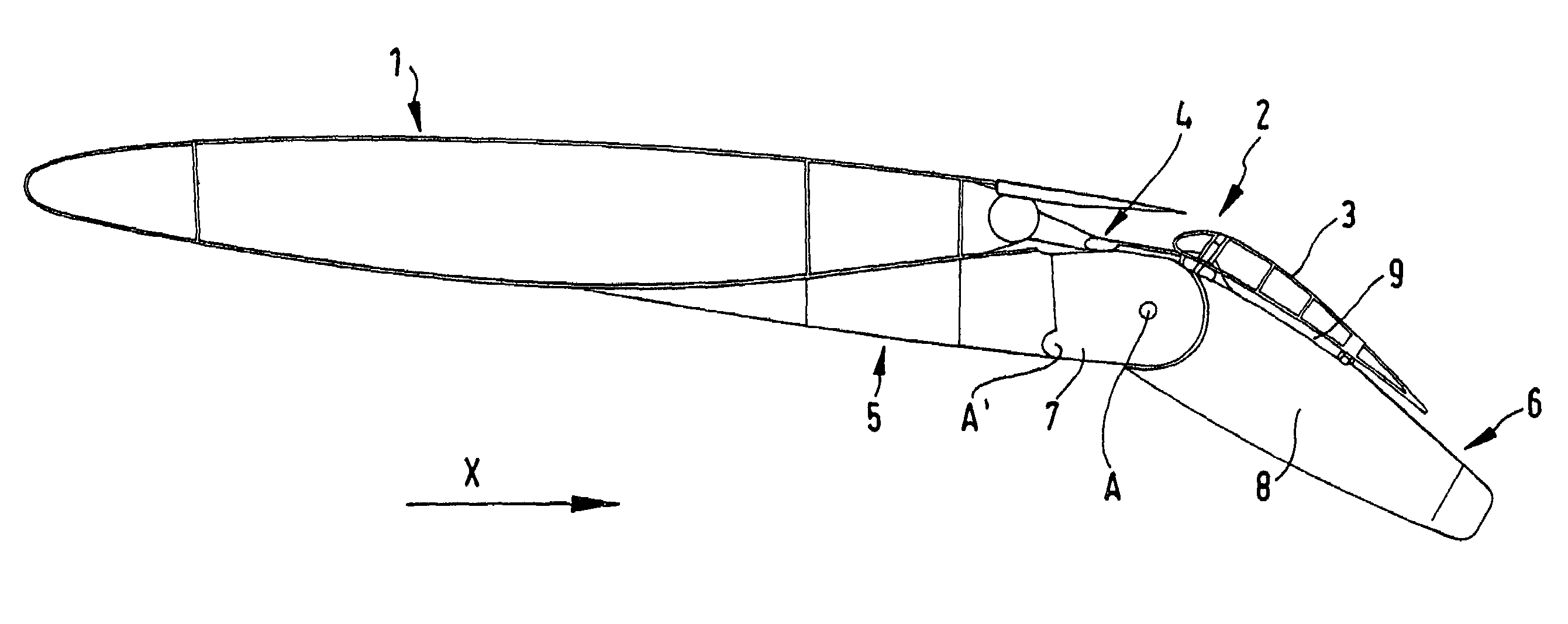
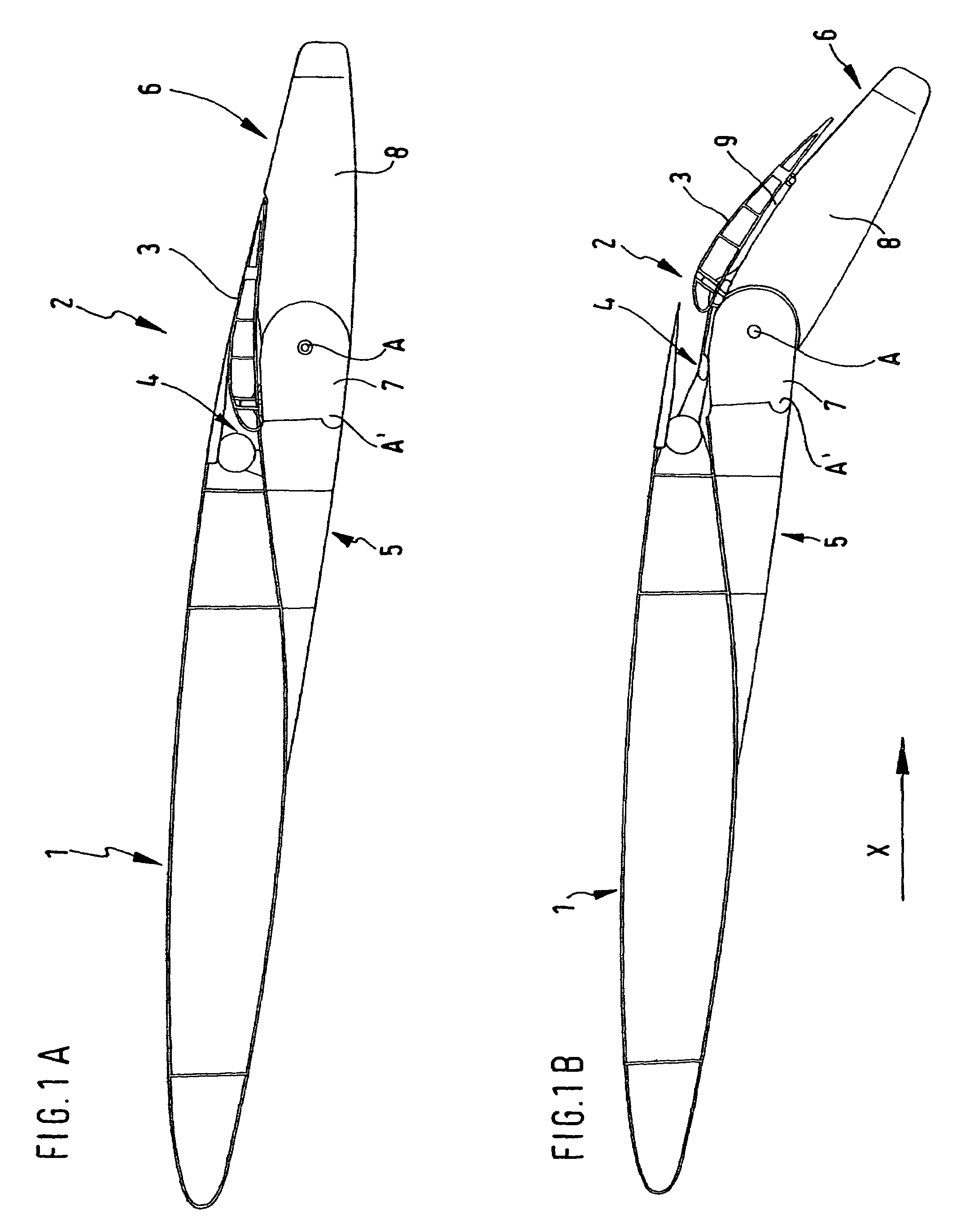
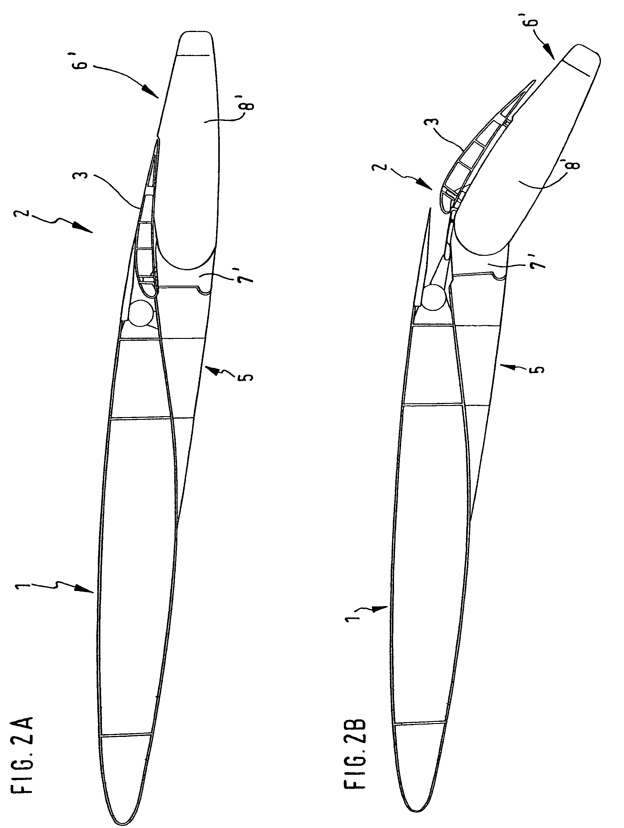
[0029]FIG. 1A shows in cross-section a wing 1 which, at its trailing edge in the direction of flow X (on the right in the figures), is provided with a lift flap arrangement 2. The lift flap arrangement 2 comprises at least one pivoted flap 3, for example a lift flap or landing flap. The flap 3 is mounted by at least one a...


PUM


Abstract

A structure with at least one flap connected to a wing, including: at least one drive device; at least one actuating device including a gear device coupled to the at least one drive device and the at least one flap; and a fairing housing swivellably mounted on the wing, at least partially surrounding the gear device, and coupled to the gear device, wherein actuation of the at least one drive device causes a combined translational and rotational movement of the at least one flap and a swivelling movement of at least a portion of the fairing housing. A method for pivoting a flap is also disclosed. The instant abstract is neither intended to define the invention disclosed in this specification nor intended to limit the scope of the invention in any way.

Description

CROSS-REFERENCE TO RELATED APPLICATIONS[0001]The present application claims priority under 35 U.S.C. § 119 of German Patent Application No. 10 2005 016 639.3 filed Apr. 11, 2005, the disclosure of which is expressly incorporated by reference herein in its entirety.BACKGROUND OF THE INVENTION[0002]1. Field of the Invention[0003]The present invention relates to a wing with extendable aerodynamic pivoted flaps, in particular lift flaps.[0004]2. Discussion of Background Information[0005]In previous known wings, the lift flaps comprise at least one roller carriage, which is provided with rollers guided by a connecting link in a C-shaped rail provided on the structure of the wing. This connecting link guide predetermines the movement path of the lift flaps. Since all of the aerodynamic forces acting on a lift flap have to be supported on the rail via the rollers, it is necessary to configure the rail so that it is extremely stable, resulting in a high weight. The reason for this lies in t...

Claims


Application Information

Patent Timeline
Patent Type & Authority Patents(United States)
IPC IPC(8): B64C9/00
CPCB64C9/16B64C9/18Y02T50/44Y02T50/40B64C9/02
Inventor PEREZ-SANCHEZ, JUAN
Owner AIRBUS DEFENCE & SPACE
Why Eureka
Try Eureka