Tool and a cutting insert for chip removing machining

a technology of cutting inserts and cutting edges, which is applied in the direction of cutting inserts, manufacturing tools, shaping cutters, etc., can solve the problems of reducing machining precision, affecting stability and position of cutting inserts, and affecting the cutting edge in relation to the basic body to such a large extent, so as to improve the interface, the effect of absorbing considerable cutting forces and the greatest need for stability

Inactive Publication Date: 2009-03-31
SANDVIK INTELLECTUAL PROPERTY AB
View PDF14 Cites 19 Cited by
  • Summary
  • Abstract
  • Description
  • Claims
  • Application Information

AI Technical Summary

Benefits of technology

[0008]The present invention aims at overcoming the above-mentioned problems, by providing a cutting tool having an improved interface between the basic body of the tool and the individual cutting insert. Therefore, a primary object of the invention is to provide a tool having an interface that, on one hand, can fix the cutting insert stably in such a way that the active cutting edge of the cutting insert is reliably located in a correct, non-overdetermined position in relation to the basic body, and, on the other hand, can absorb considerable cutting forces in the area where the need for stability is the greatest, viz. in the immediate vicinity of the corner of the cutting insert that includes the active cutting edge. An additional object is to provide an interface that not only locates the cutting insert in the desired way initially in connection with the mounting, but also can retain the stable fixation of the cutting insert under the severe stresses that the cutting insert is subjected to during the chip removing machining. In addition to presenting an improved abutment for such forces that act in the direction from above and down into the cutting insert, the interface should prevent the cutting insert from becoming translated and rotated, respectively, in relation to the basic body. It is also an object to provide an interface that guarantees the desired properties in respect of the positional accuracy and capacity of transferring force, without the manufacture of the basic body and cutting insert of the tool being made more difficult or more expensive. In particular, the cutting insert should, if required, be possible to manufacture by direct pressing, i.e., without the need of expensive grinding operations.
[0010]In another embodiment, the invention provides a cutting insert of a tool for chip removing machining, including a connecting surface in which male- and / or female-like engagement means are formed. The cutting insert has a geometrical reference locus, in which a tightening force is applicable to the cutting insert, as well as a corner having a cutting edge. A first engagement means is spaced apart from the reference locus and has a flank surface having a rotationally symmetrical and tapering basic shape to position the cutting insert in relation to a point spaced apart from the reference locus and prevent translation of the cutting insert in arbitrary force-action directions in a plane parallel to the connecting surface. A second engagement means, spaced apart from the reference locus, is provided to counteract rotation of the cutting insert around the first engagement means.

Problems solved by technology

This means that the active edge of the cutting insert very well may end up in the desired position if the outcome of the insert production is good, but when the insert production is not good (so far that the cutting insert has swollen and become longer, or shrunk and become shorter, than intended), the position of the cutting edge in relation to the basic body may deviate to such a high extent from the desired position that the machining precision will be reduced.
However, in practice, the stability and position of the cutting insert are affected by a number of unforeseeable factors, one of the most difficult to master being the varying outcome of the manufacture of the cutting inserts.
As long as the outcome gives a good, nominal dimensional accuracy, the intended and calculated surface or line contact, among other things, is obtained between the flanks of the ridges and grooves along the entire length of the flanks, but as soon as even moderate form defects arise, there is a risk that the contact between the flanks is reduced to point contacts or partial line contact.
This may in turn result in the cutting insert, initially as well as during operation, being positioned incorrectly in relation to the basic body (by so-called overdetermination), and that the transfer of force between the cutting insert and the basic body becomes inferior.
However, in these cases, the female-like engagement means are only partly round seatings or seating surfaces, which are open laterally, and which therefore cannot absorb lateral displacement forces in arbitrary radial directions.
In practice, however, the screw lacks the capability of rotation-securing the cutting insert in a position in which the active cutting edge of the cutting insert reliably can retain an exact space position in relation to the basic body, since the screw, via the male thread thereof, has a certain play in relation to the female thread of the basic body, and may as well be deflected by the cutting forces.

Method used


Image

  • Tool and a cutting insert for chip removing machining
  • Tool and a cutting insert for chip removing machining
  • Tool and a cutting insert for chip removing machining

Examples


Embodiment Construction

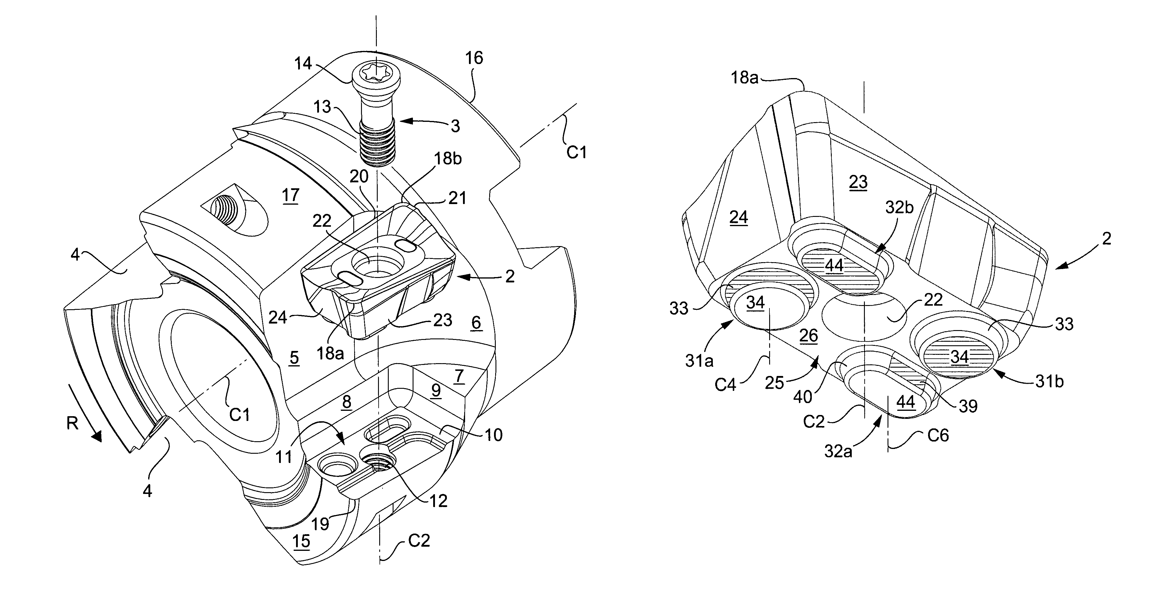
[0031]In FIG. 1, a tool for chip removing machining (cutting tool) is shown, which includes a basic body 1 and a cutting insert 2, that is fixable in the basic body by means of a tightening member 3, which, in this case, is in the form of a screw. In the example, the tool is rotatable and is a milling cutter, more precisely an end or face mill, which includes a plurality of chip pockets 4 in which equally many cutting inserts 2 can be mounted, only one of which is shown in FIG. 1. The basic body 1 is rotatable around a center axis designated C1.

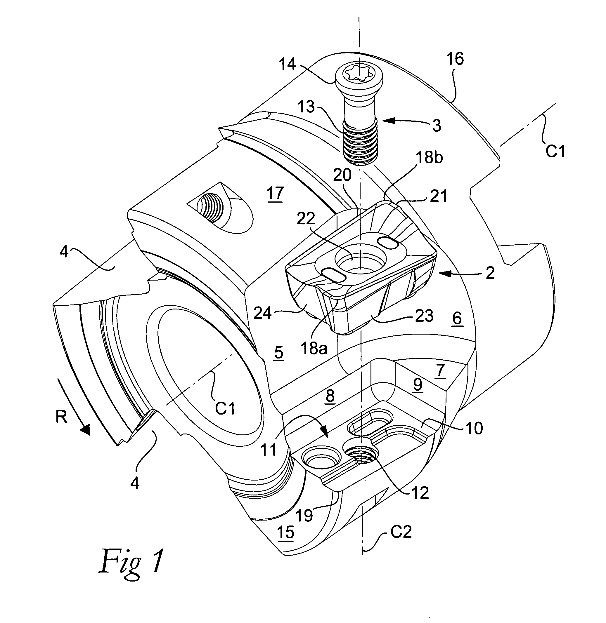
[0032]In this case, the individual chip pocket 4 is delimited by a side surface 5, a concavely arched end surface 6, and a planar shoulder surface 7, which transforms into a countersink, which in turn is delimited by a side surface 8, an end surface 9, as well as a shoulder surface 10, which in this case is planar. Together with countersunk seatings and part surfaces, which will be described in detail below, the shoulder surface 10 is include...


PUM

PropertyMeasurementUnit
cone angleaaaaaaaaaa

Abstract

The invention relates to a cutting tool including a basic body and a cutting insert detachably connected to the basic body via an interface, which includes a pair of co-operating connecting surfaces in which engagement means are included, which may be in the form of knobs and seatings. A knob and a co-operating seating have a rotationally symmetrical, conical shape to prevent translation of the cutting insert in the plane of the interface. Another knob ensures that the cutting insert cannot be rotated in relation to the conical knob. Simultaneously, ample bearing surfaces abut against co-operating support surfaces in a connecting surface. In such a way, the cutting insert is fixed in a stable, non-overdetermined position in the basic body. Furthermore, the invention relates to a cutting insert as such.

Description

[0001]This application claims priority under 35 U.S.C. § 119 to Sweden Patent Application No. 0600876-7, filed on Apr. 20, 2006, the disclosure of which is incorporated by reference herein in its entirety.FIELD OF THE INVENTION[0002]The present invention relates generally to a tool for chip removing machining of the type that includes a basic body and a cutting insert, which is detachably connected to the basic body via an interface, which includes, on one hand, a first connecting surface included in the basic body and in which one or more female- and / or male-like, primary engagement means are formed, and, on the other hand, a second connecting surface included in the cutting insert and in which one or more secondary, male- and / or female-like engagement means are formed for the engagement with the primary engagement means in the first connecting surface, the connecting surfaces of the cutting insert and the basic body having a common geometrical reference locus, and the cutting inse...

Claims


Application Information

Patent Timeline
Patent Type & Authority Patents(United States)
IPC IPC(8): B23C5/00B23C1/00
CPCB23C5/06B23C5/2221B23C2200/161B23C2200/164Y10T407/23B23C2210/168Y10T407/22Y10T407/227B23C2210/163B23C5/2213B23C5/22B23B27/16B23B51/04B23B27/164B23C5/2247B23B51/00B23B51/0007B23B51/0004B23B2205/04B23C5/2304
Inventor ANDERSSON, CLAESENGLUND, KJELLEDLER, DANIEL
Owner SANDVIK INTELLECTUAL PROPERTY AB
Why Eureka
Try Eureka