Eureka AIR delivers breakthrough ideas for toughest innovation challenges, trusted by R&D personnel around the world.

Method for operating biopsy device

Inactive Publication Date: 2009-03-31
DEVICOR MEDICAL PROD
View PDF16 Cites 756 Cited by
  • Summary
  • Abstract
  • Description
  • Claims
  • Application Information

AI Technical Summary

Benefits of technology

[0014]A method according to the present invention includes the steps of: translating the cutter distally until the translation of the cutter is stopped at an extended position; recording the extended position; translating the cutter from the extended position proximally until the translation of the cutter is stopped at a retracted position proximal to the extended position; recording the retracted position. The method further comprises the step of rotating the cutter to a rotation speed while the cutter is located at the retracted position; determining if the rotation speed is within a predetermined rotation speed range; providing a feedback signal on the display allowing an operator to progress to the next procedural step when the rotation speed is within the predetermined rotation speed range.

Problems solved by technology

The method is less intrusive than most other sampling techniques, however, it has limited application since the structure of tissue excised by aspiration is destroyed leaving only individual cells for analysis (cytology) and not the tissue structure for analysis (pathology).
The type of biopsy used depends mainly on various factors, and no single procedure is ideal for all cases.
However, if the procedure is automated as described in those references, the surgeon loses the benefit of the tactile feedback, which results when the cutter is advanced and retracted manually.
This system as disclosed however does not compensate for the aforementioned problem of the surgeon's lack of tactile feedback and control as the cutter reaches its limits of distal and proximal travel.
Unfortunately the reaction time for the cable rotational sensors to detect the obstruction, send a message to the control apparatus, and the control apparatus terminate power to the cable drive motors may be too long to prevent the flexible, rotatable drive cables from twisting or “winding” do to the cutter's sudden and unexpected stop.
If the user is not grasping the biopsy device tightly there is the risk the biopsy probe could inadvertently move and cause discomfort to the patent.
Another shortfall of this control system relates to its inability to compensate for different probe unit / drive unit combinations.

Method used


Image

  • Method for operating biopsy device
  • Method for operating biopsy device
  • Method for operating biopsy device

Examples


Embodiment Construction

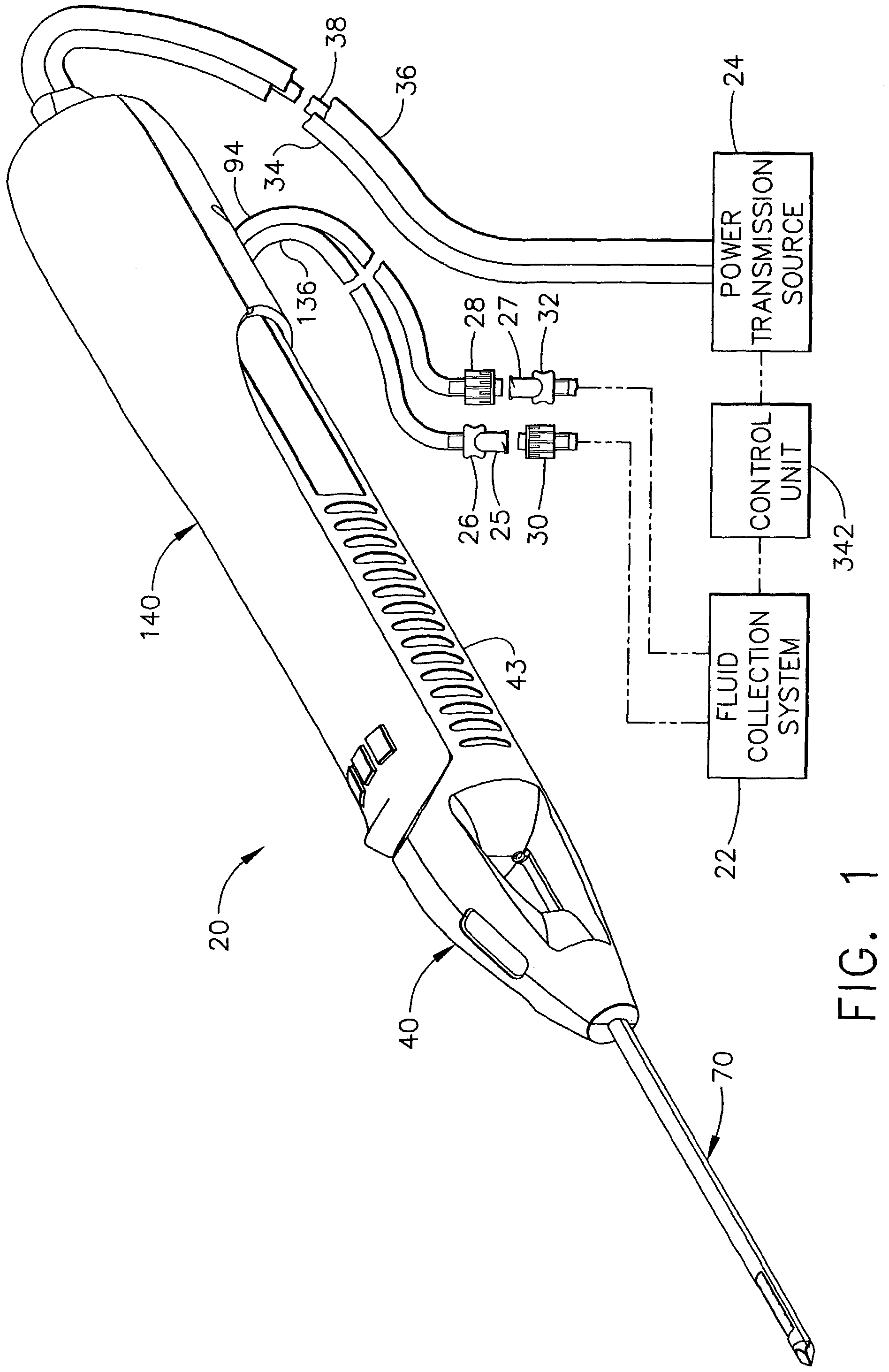
[0040]FIG. 1 shows a core sampling biopsy instrument comprising a probe assembly 40, a holster 140, a fluid collection system 22, a control unit 342, and a power transmission source 24. Probe assembly 40 is detachably connected to holster 140. Together they constitute a lightweight, ergonomically shaped, hand manipulatable portion referred to as a handpiece 20. Probe assembly 40 includes a piercer 70 extending distally from a hollow handle 43. Probe assembly 40 is fluidly connected to fluid collection system 22 by a first vacuum tube 94 and a second vacuum tube 136. First and second vacuum tubes are detachably connected to fluid collection system 22 by a first connector 27 and a second connector 25, respectively. First connector 27 has a male portion 32 and a female portion 28 attached to first vacuum tube 94. Second connector 25 has a female portion 30 and a male portion 26 attached to second vacuum tube 136. Connector portions, 26, 28, 30, and 32 are attached in this manner to pre...


PUM


Abstract

A method is provided for calibrating a surgical biopsy system. The biopsy system includes a biopsy instrument and control unit. The biopsy instrument includes a piercer, rotatable cutter, and a port for receiving tissue samples. The method comprises the steps of translating the cutter distally until the translation of the cutter is stopped at an extended position and recording the extended position. The cutter is then translated from the extended position proximally until the translation of the cutter is stopped at a retracted position proximal to the extended position. The retracted position is recorded. The method further comprises the step of rotating the cutter to a rotation speed while the cutter is located at the retracted position and, if determined that the rotation speed is within a predetermined rotation speed range, a feedback signal is provided on the display allowing the operator to progress to the next procedural step.

Description

[0001]This divisional application claims priority to U.S. patent application Ser. No. 09 / 910,581, filed Jul. 20, 2001, now U.S. Pat. No. 6,585,664, “Calibration Method for an Automated Surgical Biopsy Device” to Mark Burdoff et al.[0002]This application is related to the following co-pending U.S. patent application: Ser. No. 08 / 825,899 filed on Apr. 2, 1997. This application is further related to the following co-pending U.S. patent applications, which are hereby incorporated herein by reference: Ser. No. 09 / 543,122 filed on Oct. 23, 1998; Ser. No. 09 / 466,391 filed Dec. 17, 1999; Ser. No. 09 / 466,491 filed Dec. 17, 1999.FIELD OF THE INVENTION[0003]The present invention relates, in general, to a method of calibrating a biopsy system and, more particularly, to a method of calibrating the translation and rotation of a cutter in a biopsy instrument. The method may further be used to determine the correct selection of probe size for the software installed in the control unit.BACKGROUND OF...

Claims


Application Information

Patent Timeline
IPC IPC(8): A61B10/00A61B17/32A61B10/02
CPCA61B10/0275A61B10/0266A61B2010/0208A61B10/02
Inventor BURDORFF, MARK A.HIBNER, JOHN A.DLUGOS, DANIEL F.GLEASON, SCOTT A.SCHMIDT, BRIAN W.
Owner DEVICOR MEDICAL PROD
Why Eureka
Eureka Blog
Learn More