Ultraviolet disinfection device

a disinfection device and ultraviolet light technology, applied in the field of ultraviolet light disinfection, to achieve the effect of effective disinfection of objects, reducing leakage of ultraviolet light, and being convenient and safe to us

Inactive Publication Date: 2009-03-31
CHOR YUE LAI
View PDF6 Cites 20 Cited by
  • Summary
  • Abstract
  • Description
  • Claims
  • Application Information

AI Technical Summary

Benefits of technology

[0005]The primary objective of the present invention is to provide an ultraviolet disinfection device for effective disinfection of objects such as toothbrushes and chopsticks. Another objective is to provide an ultraviolet disinfection device that is both convenient and safe to use. It can both tremendously reduce leakage of the ultraviolet light, thus protecting the user's eyes, and yet maintains good disinfection capability.
[0006]The above objectives can be accomplished in the ultraviolet disinfection device of this invention. The most salient feature of this ultraviolet disinfection device is the protective shield which surrounds the ultraviolet lamp that generates the germicidal UV light. The said protective shield provides two protective functions. Firstly, it protects the user's eyes by preventing the ultraviolet light generated by the ultraviolet lamp from leaking directly through the openings of the top cover of the ultraviolet disinfection device. Secondly, it protects the ultraviolet lamp, which it surrounds, from being damaged by mechanical forces exerted by any object that is inserted in any of the disinfection cells of the ultraviolet disinfection device.
[0016]By this simple design, this invention can conveniently disinfect personal belongings and promote personal hygiene by simply inserting any long objects such as toothbrushes and chopsticks into a disinfection cell of this device. Meanwhile, the protective shield that surrounds the ultraviolet lamp greatly reduces the leakage of ultraviolet light, thus preventing damage to the user's eyes. Yet it still provides enough disinfection power. Thus, in addition to the convenience of usage, this ultraviolet disinfection device also protects the user's health.

Problems solved by technology

Secondly, it protects the ultraviolet lamp, which it surrounds, from being damaged by mechanical forces exerted by any object that is inserted in any of the disinfection cells of the ultraviolet disinfection device.

Method used


Image

  • Ultraviolet disinfection device
  • Ultraviolet disinfection device
  • Ultraviolet disinfection device

Examples


Embodiment Construction

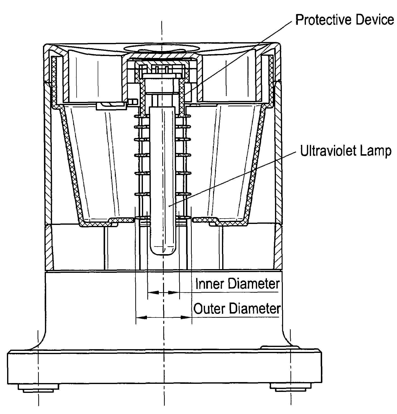
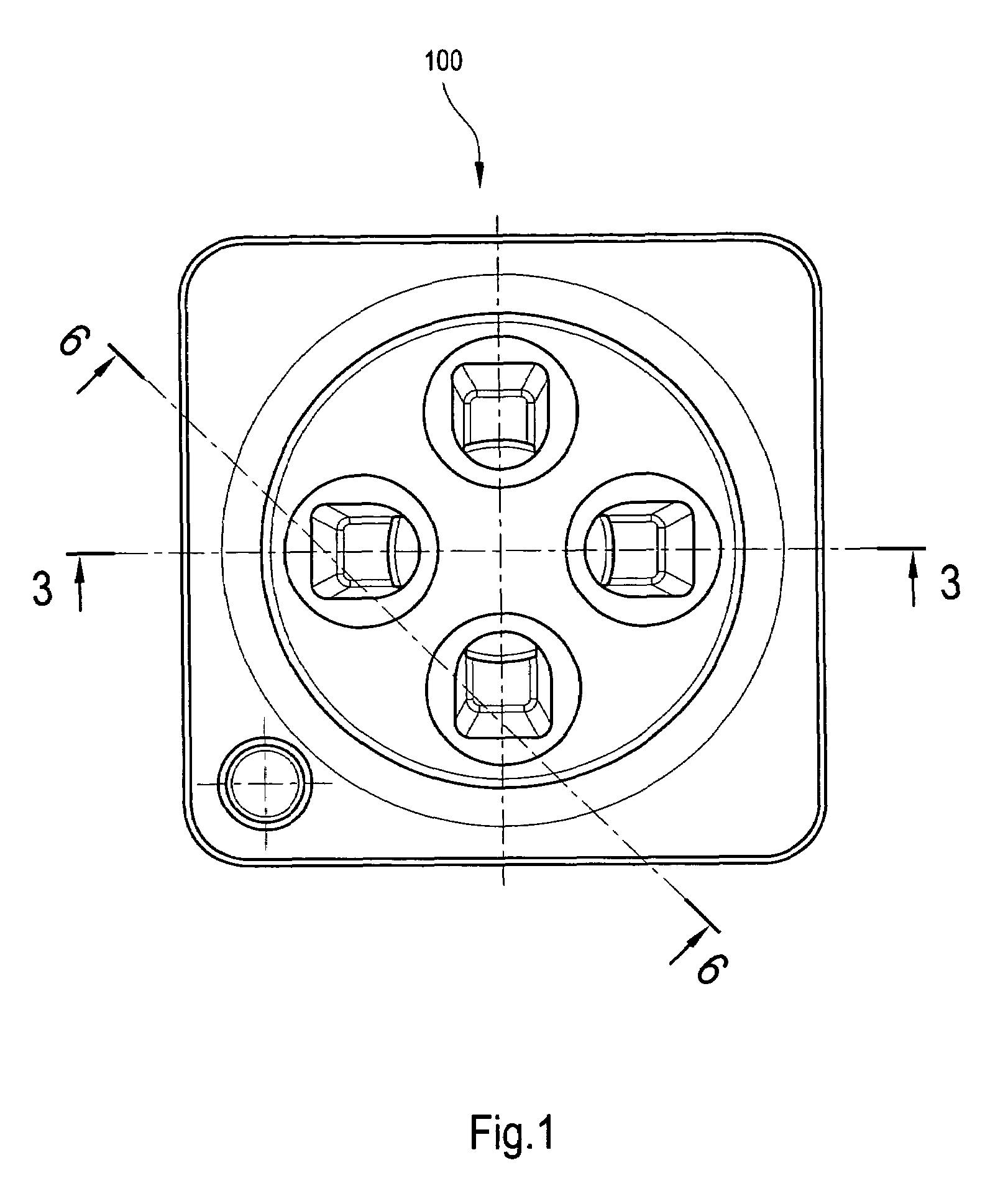
[0030]The invention is illustrated through a description of a preferred embodiment in which the device is designed around a cylindrical protective shield. Please refer to FIG. 1 first. This figure shows the top view of this ultraviolet disinfection device 100. In this embodiment of the invention, there are four disinfection cells 35 and therefore four openings on the top cover of the device.

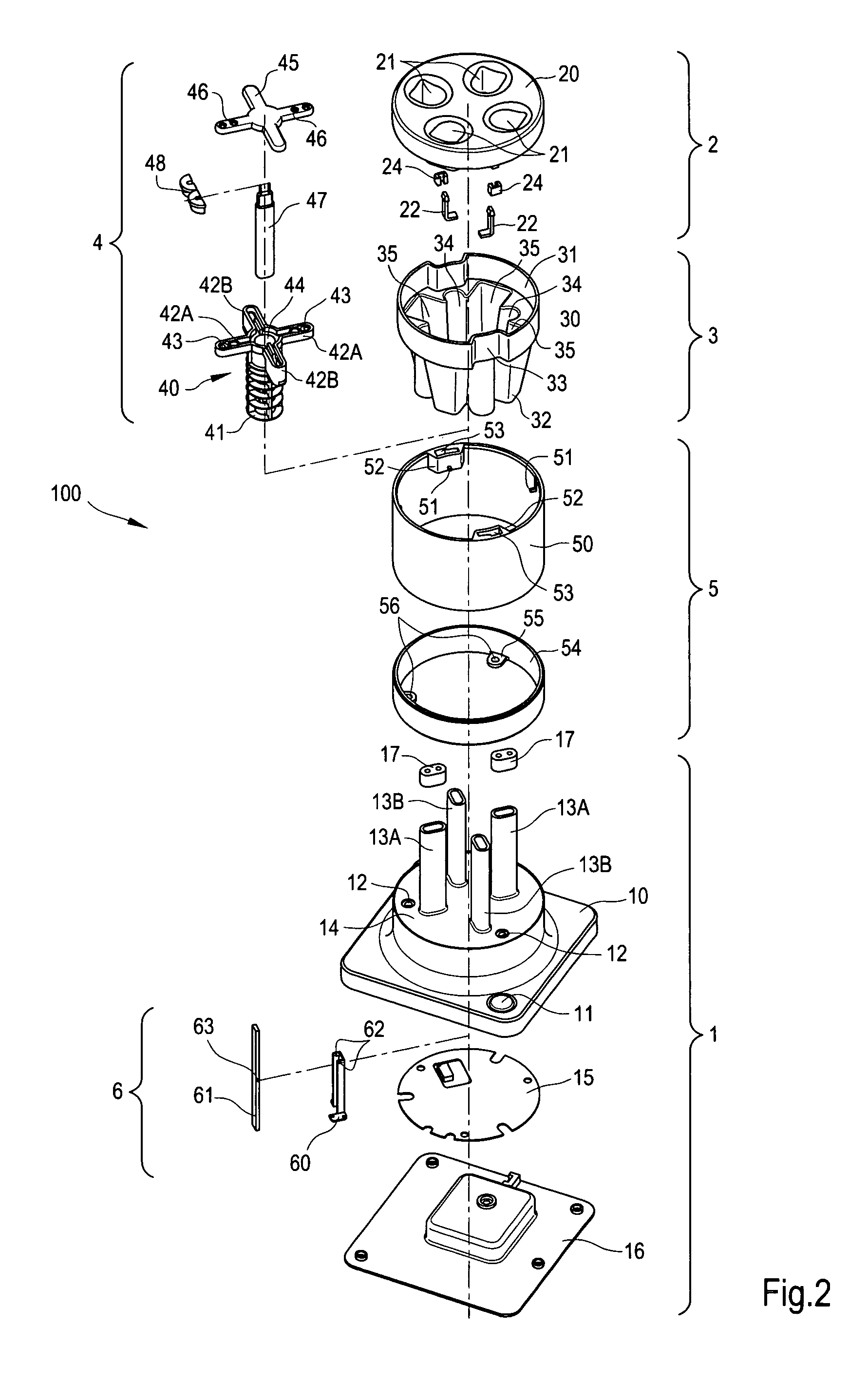
[0031]Please then refer to FIG. 2 and FIG. 3. FIG. 2 is an exploded view of the preferred embodiment of the ultraviolet disinfection device that is shown in FIG. 1. FIG. 3 is a sectional view along the axis 3-3 of FIG. 1. The device has a base 1 at the bottom of the ultraviolet disinfection device 100. At the bottom of base 1 is a base bottom cover 16. Above the base bottom cover 16 is a circuit board 15. There is a micro-switch 18 inside the base 1 (as shown in FIG. 6). The micro-switch 18 is connected to the circuit board 15. Above the circuit board 15 is a base body 10.

[0032]The top surface of...


PUM

PropertyMeasurementUnit
thicknessaaaaaaaaaa
thicknessaaaaaaaaaa
outer diameteraaaaaaaaaa

Abstract

The invention relates to a UV-lamp sterilizing appliance that is used to destroy bacteria. The appliance presents a simple design which can facilitate the sterilization of any elongate personal article such as toothbrush, chopsticks and the like for sanitation by simply putting them into the appliance. The appliance also includes a protective shield surrounding the UV-lamp. The shield is designed to prevent any damage to the user's sight from the leakage of the UV-lamp radiation and also to retain the capacity to destroy bacteria sufficiently. The shield also protects the lamp from damage. Thereby the appliance according to the invention can be used easily and safeguards the user's health.

Description

TECHNICAL FIELD OF THE INVENTION[0001]This invention is a disinfection device, to be specific, an Ultraviolet Disinfection Device that uses ultraviolet light to kill germs and includes a protective shield.BACKGROUND OF THE INVENTION[0002]It is well known that ultraviolet (a.k.a. UV) light of a particular range of wavelength, called germicidal UV light, can destroy germs. The Ultraviolet Disinfection Device of the present invention is a device that kills germs by means of the germicidal UV light that is generated by the ultraviolet lamp. Elongated personal articles, such as toothbrush and chopsticks, can be disinfected by inserting them into the device.[0003]Currently, there are two types of ultraviolet disinfection devices for disinfecting long objects such as toothbrushes and chopsticks. One type uses an enclosed case, with several hooks or other fixtures inside for hanging or holding the objects to be disinfected. The user only need to place the objects properly, close the cover, ...

Claims


Application Information

Patent Timeline
Patent Type & Authority Patents(United States)
IPC IPC(8): H01J37/20A61LA61L2/10B01J
CPCA61L2/10
Inventor CHOR, YUE LAI
Owner CHOR YUE LAI
Why Eureka
Try Eureka