Efficient conversion of heat to useful energy

a conversion efficiency and heat conversion technology, applied in steam engine plants, machines/engines, mechanical equipment, etc., can solve the problems of not being efficiently raised, the temperature to which the conventional dcss would cool a typical spent stream would ordinarily be too low to be efficiently utilized, etc., to achieve efficient use of waste heat and efficient incorporation of dcss

Active Publication Date: 2009-04-14
RECURRENT ENG LLC
View PDF13 Cites 46 Cited by
  • Summary
  • Abstract
  • Description
  • Claims
  • Application Information

AI Technical Summary

Benefits of technology

[0012]The present invention solves one or more of the foregoing problems in the prior art with systems and apparatus configured to efficiently use more waste heat than possible in prior heat transfer systems. In particular, the present invention provides for the use of a “low temperature tail” of a brine heat source in a heat transfer system, at least in part by efficiently incorporating a DCSS along with additional heat exchange apparatus.
[0014]Accordingly, a heat transfer system in accordance with the present invention can convert a greater amount of heat from the heat source into useful energy, and can do so with significantly more energy efficiency than prior heat transfer systems.

Problems solved by technology

Unfortunately, while use of a DCSS could efficiently cool a spent stream, the temperature to which the conventional DCSS would cool a typical spent stream would ordinarily be too low to be efficiently utilized.
That is, the conventional DCSS would cool the spent stream to a temperature that is so low that it could not be efficiently raised to a high enough temperature later on as a working stream.

Method used


Image

  • Efficient conversion of heat to useful energy
  • Efficient conversion of heat to useful energy
  • Efficient conversion of heat to useful energy

Examples


Embodiment Construction

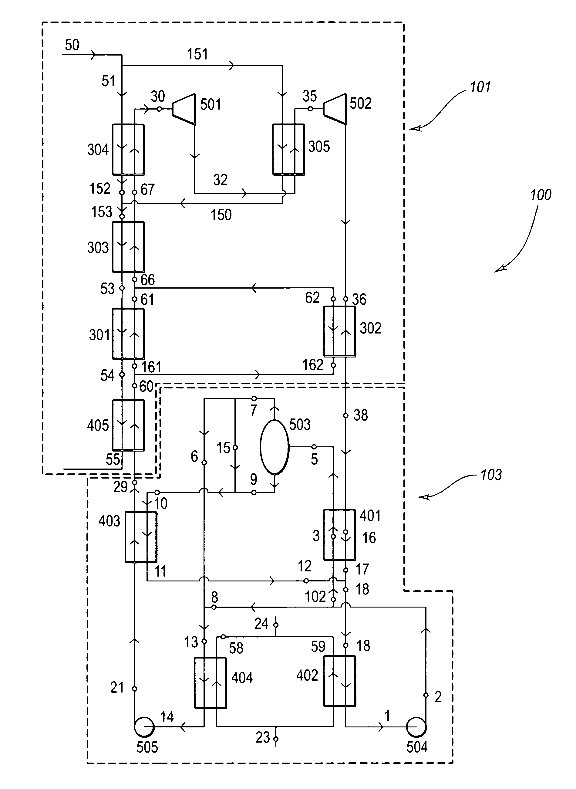
[0019]The present invention extends to systems and apparatus configured to efficiently use more waste heat than possible in prior heat transfer systems. In particular, the present invention provides for the use of a “low temperature tail” of a brine heat source in a heat transfer system, at least in part by efficiently incorporating a DCSS along with additional heat exchange apparatus.

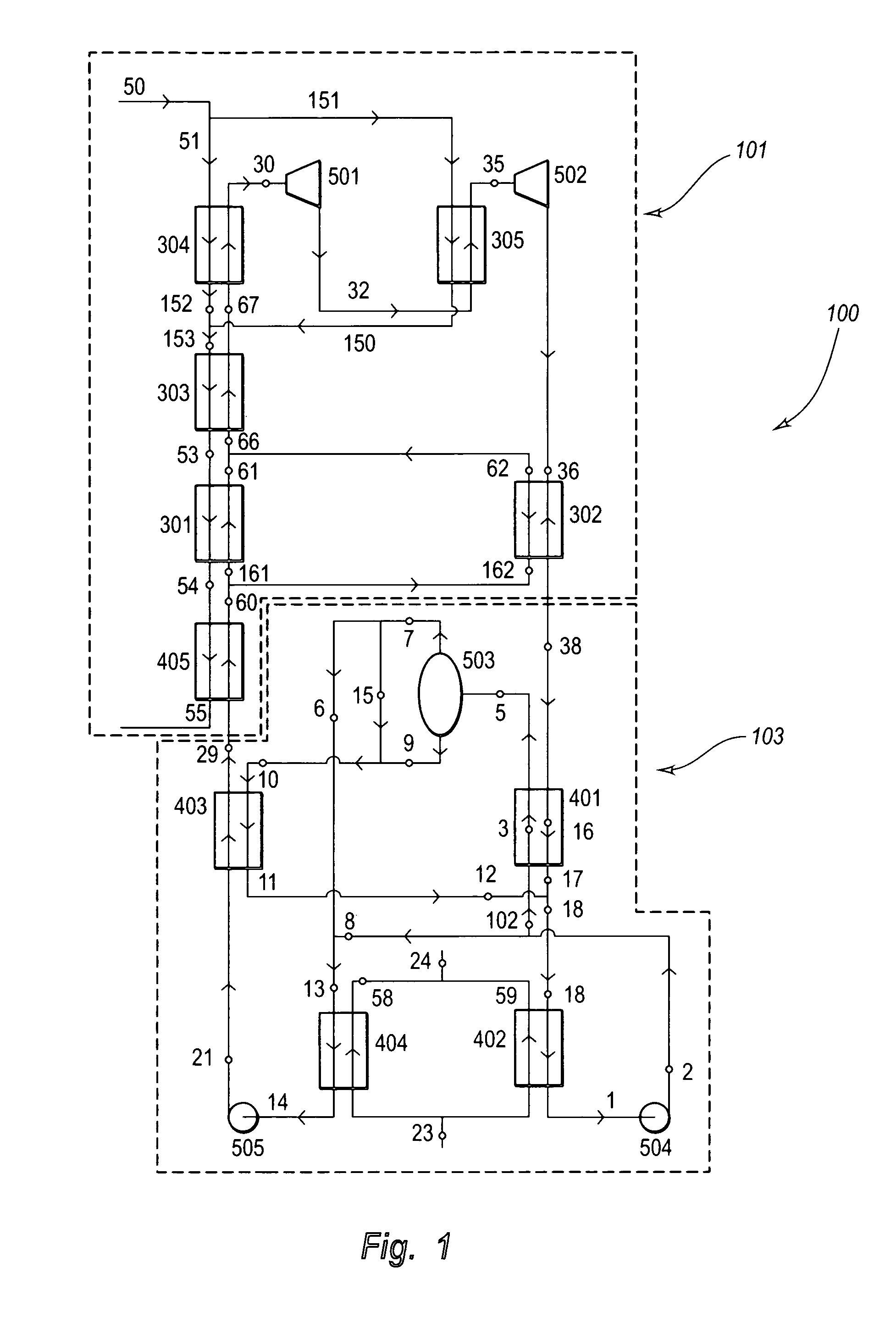
[0020]For example, FIG. 1 illustrates one embodiment of the present invention in which a heat transfer system 100 comprises a power sub-system 101 that is coupled to a cooling system, such as Distillation Condensation Sub-system (“DCSS”) 103. The power sub-system 101 can be thought of generally as heating the multi-component stream to a point at which the fluid multi-component stream becomes an at least partially a vapor working stream. By contrast, the DCSS 103 can be thought of generally as cooling a post expansion spent stream to a cooled fluid stream, as well as heating the fluid stream where appro...


PUM


Abstract

A heat transfer system includes a power sub-system configured to receive a heat source stream, and one or more heat exchangers configured to transfer heat from the heat source stream to a working stream. The working stream is ultimately heated to a point where it can be passed through one or more turbines, to generate power, while the heat source stream is cooled to a low temperature tail. A distillation condensation sub-system cools the spent stream to generate an intermediate stream and a working stream. The working stream can be variably heated by the intermediate stream so that it is at a sufficient temperature to make efficient use of the low temperature tail. The working stream is then heated by the low temperature tail, and subsequently passed on for use in the power sub-system.

Description

CROSS-REFERENCE TO RELATED APPLICATIONS[0001]This application claims priority to and the benefit of Australian Provisional Patent Application No. 2004903961, filed on Jul. 19, 2004, entitled “METHOD FOR CONVERTING HEAT TO USEFUL ENERGY”; and also claims priority to and the benefit of Australian Application No. 2005203045, filed on Jul. 13, 2005, entitled “METHOD FOR CONVERTING HEAT TO USEFUL ENERGY”, the entire specifications of both applications are incorporated herein by reference.BACKGROUND OF THE INVENTION[0002]1. The Field of the Invention[0003]The present invention relates to systems, methods and apparatus configured to implement a thermodynamic cycle via countercurrent heat exchange. In particular, the present invention relates to generating electricity by heating a multi-component stream with a heat source stream at one or more points in a thermodynamic cycle.[0004]2. Background and Relevant Art[0005]Some conventional heat transfer systems allow heat that would otherwise be ...

Claims


Application Information

Patent Timeline
Patent Type & Authority Patents(United States)
IPC IPC(8): F01K25/06
CPCF01K25/065
Inventor PELLETIER, RICHARD I.
Owner RECURRENT ENG LLC
Why Eureka
Try Eureka