Microjet module assembly

a technology of micro-jet modules and modules, which is applied in the direction of cooling/ventilation/heating modifications, semiconductor device details, semiconductor devices, etc., can solve the problems of large power flux, large thermal gradient, and inability to meet the demands of modern electronic devices, and achieve the effect of increasing thermal performan

Inactive Publication Date: 2009-04-14
GLOBALFOUNDRIES INC
View PDF17 Cites 59 Cited by
  • Summary
  • Abstract
  • Description
  • Claims
  • Application Information

AI Technical Summary

Benefits of technology

[0015]Still another object of the present invention is to provide thermal assemblies, systems and methods of making thermal assemblies having distributed microjets parallel with distributed via drain returns for impinging cooling fluid and removing spent heated fluid in a direction orthogonal to a target surface for maximizing the heat transfer rate.
[0017]Yet another object of the present invention is to provide thermal assemblies, systems and methods of making thermal assemblies that isolate the active or functional side from rest of the thermal assembly to prevent fluid leakage onto the active or functional side.
[0021]Yet another object of the present invention is to provide thermal assemblies, systems and methods of making thermal assemblies that increase the thermal performance by providing a grooved surface in association with microjets with distributed returns.
[0023]The above and other objects, which will be apparent to those skilled in art, are achieved in the present invention, which is directed to a low-pressure drop thermal assembly for thermal management of a semiconductor. This low-pressure drop thermal assembly includes a subassembly that comprises a manifold directly attached to a distributor. The manifold has an inlet opening isolated from an outlet opening, while the distributor has an inlet microjet array isolated from an outlet microjet array, whereby each inlet microjet is adjacent at least three outlet microjets. The manifold is attached to the distributor such that the inlet opening communicates with the inlet microjet array and the outlet opening communicates with the outlet microjet array. A substrate surface is in communication with this subassembly, whereby a semiconductor device is on the substrate surface. The semiconductor device has a first and second surface. The first surface is orthogonal to an input, output direction flow of a fluid input by the microjet input array and output by the distributed microjet outlet array, while the second surface has hierarchy thereon (e.g., chips, interconnects, modules, integrated circuits, transistors, resistors, and the like). A cavity resides between the subassembly and the substrate surface, whereby a seal of such cavity protects the hierarchy from the fluid.

Problems solved by technology

It has been found that conventional thermal technologies for cooling electronic devices, such as, heat spreaders, heat sinks, and associated thermal interfaces, are generally not scalable to meet the demands of modern electronic devices.
Under such processing conditions, if the cooling method is primarily based on a heat conduction mechanism, the power flux will be undesirably large such that it generates significant thermal gradients along the cooling axis.
Yet, current higher cooling solutions often require a high fluid flow rate, which in turn, results in an undesirable increase in pressure drop on the cooler (fluid inlet to the outlet pressure difference).
As such, the extendibility of conventional cooling solutions is deleteriously limited by the pressure drop required to operate modern electronic devices having high power flux situations.
This undesirably results in uneven cooling across the surface of the electronic component, especially from the center to the edge of the electronic component.
These lateral drains 5 are insufficient for cooling high power flux situations due to the lack of proper spent fluid drainage.
Attempts have been made to resolve the resulting temperature gradient by placing the inlet fluid jets close to one another, but when these inlet microjets are placed too close together interactions between adjacent jets degrades the thermal performance of the array.
Current fluid jet arrays are also impractical for cooling high power flux situations due to their structural designs.
Drain velocities above 50% of the fluid jet array velocity undesirably force the fluid jets to move away from the desired orthogonal orientation, thereby reducing the heat transfer rate by more than 20% relative to the heat transfer rate of a fully orthogonally oriented jet.
This problem increases significantly in two-phase coolers, where the gas phase volumetric flow can be up to three orders of magnitude larger than the liquid flow.
Another disadvantage of conventional heating and / or cooling devices is that they do not protect the components on the semiconductor device in need of thermal management, such as, chips, interconnects, modules, integrated circuits, transistors, resistors, and the like, which reside on the semiconductor device surface opposite the surface being impinged.

Method used


Image

  • Microjet module assembly
  • Microjet module assembly
  • Microjet module assembly

Examples


Embodiment Construction

)

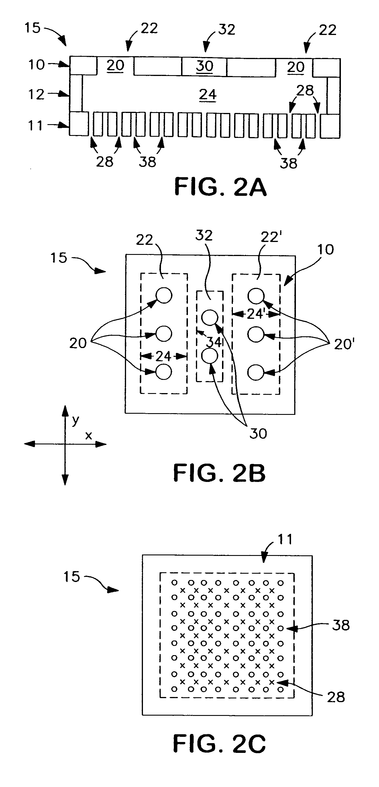
[0037]In describing the preferred embodiment of the present invention, reference will be made herein to FIGS. 2A-6 of the drawings in which like numerals refer to like features of the invention.

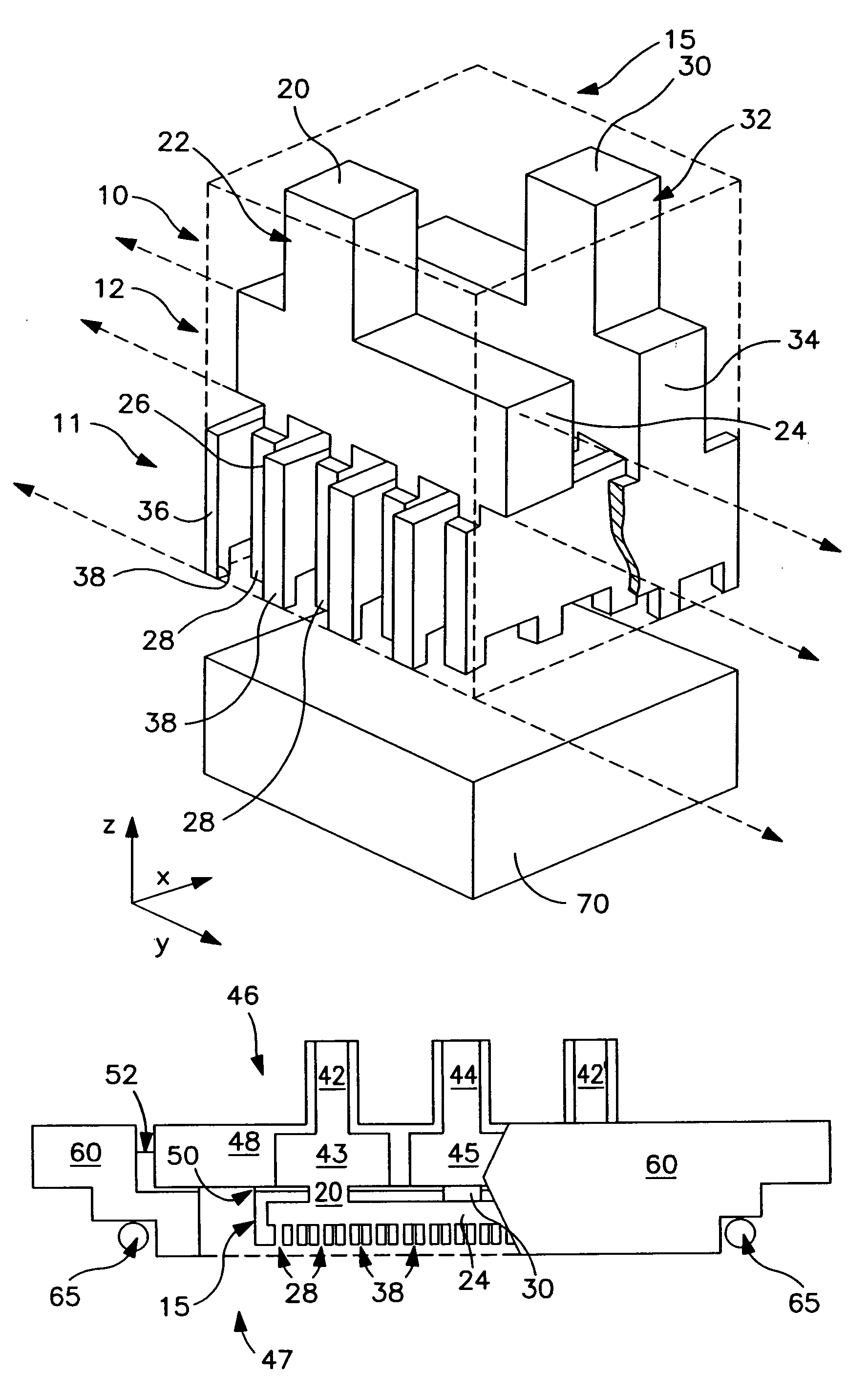
[0038]The present invention is directed to low-pressure drop thermal assemblies, and methods of making the same, whereby these assemblies have a liquid impingement microjet inlet array isolated from a distributed microjet outlet or drain array for use in high power flux situations. These assemblies advantageously maximize the heat transfer rate in a high power dissipating assembly, and simultaneously assuring the mechanical integrity by limiting the fluid pressure drop below 10 psi. The thermal assemblies of the invention also isolate the active, i.e., functional side, of the semiconductor device from the rest of the thermal assembly to prevent fluid leakage onto such active side.

[0039]As shown in FIGS. 2A-D, a fluid distribution structure 15 is an essential component of the present low-pres...


PUM


Abstract

Low-pressure drop thermal assemblies, systems and methods of making low-pressure drop thermal assemblies for use in high power flux situations. A manifold body is attached to a distributor to form a subassembly. This subassembly is in communication with a substrate surface, which has a semiconductor device in need of thermal management thereon. An enclosed cavity is formed between the target substrate surface and the subassembly, and a seal of the cavity protects critical components residing on the active surface of the semiconductor device. The distributor includes a distributed liquid impingement microjet inlet array isolated from and parallel with a distributed microjet drain array for impinging cooling fluid and removing spent heated fluid in a direction orthogonal to a target surface for maximizing the heat transfer rate, and thereby providing high cooling flux capabilities while enabling low-pressure drops.

Description

BACKGROUND OF THE INVENTION[0001]1. Field of the Invention[0002]The present invention relates to the heating and / or cooling of high power dissipating devices, such as semiconductor chips, and in particular, to a low pressure drop thermal device for microjet liquid impingement with distributed returns and methods of manufacturing the same.[0003]2. Description of Related Art[0004]It has been found that conventional thermal technologies for cooling electronic devices, such as, heat spreaders, heat sinks, and associated thermal interfaces, are generally not scalable to meet the demands of modern electronic devices. These modern electronic devices include those having increased power densities, operating frequencies and current leakages, as well as devices having small cooling fluid thermal budgets or having very high average power flux. For instance, in an electronic device having a high average power flux, a high power hot spot may dissipate 300 to 500 W / cm2, while a very high power ho...

Claims


Application Information

Patent Timeline
Patent Type & Authority Patents(United States)
IPC IPC(8): H05K7/20
CPCH01L23/4735H01L2924/09701H01L2924/0002Y10S165/908H01L2924/00
Inventor BEZAMA, RASCHID J.NATARAJAN, GOVINDARAJANSIKKA, KAMAL K.TOY, HILTON T.
Owner GLOBALFOUNDRIES INC
Why Eureka
Try Eureka