
Lightweight composite truss wind turbine blade

a wind turbine blade and composite technology, applied in the field of airfoil core structures, can solve the problems of wind power having a high proportion of up-front costs, fossil fuels such as coal and petroleum, now being shunned,

Inactive Publication Date: 2009-04-14
VESTAS WIND SYST AS
View PDF70 Cites 47 Cited by
  • Summary
  • Abstract
  • Description
  • Claims
  • Application Information

AI Technical Summary

Benefits of technology

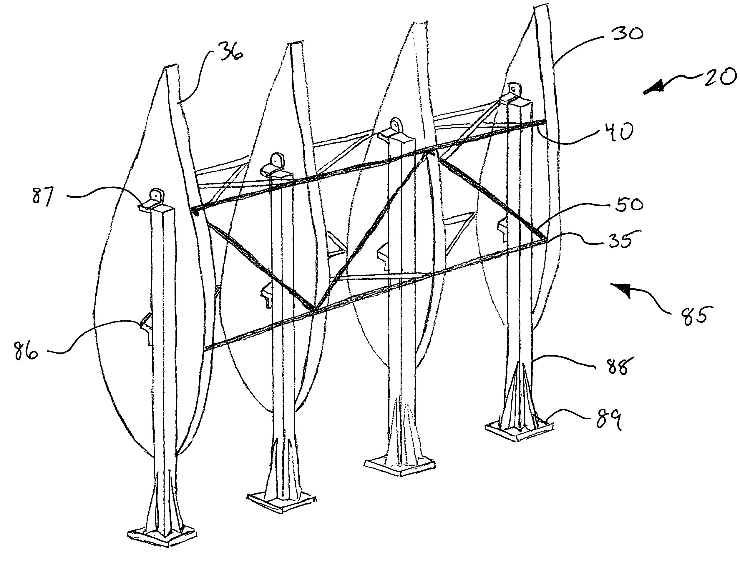
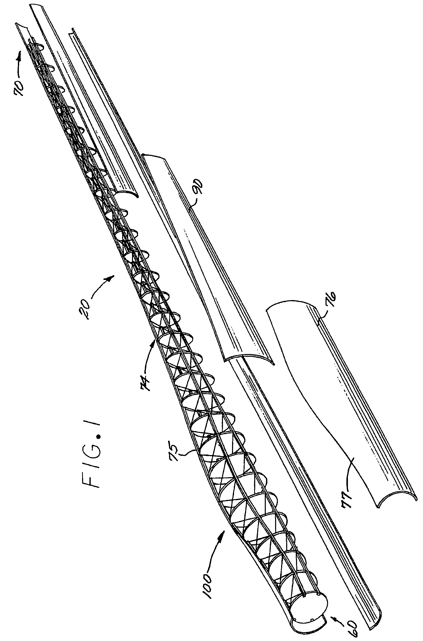
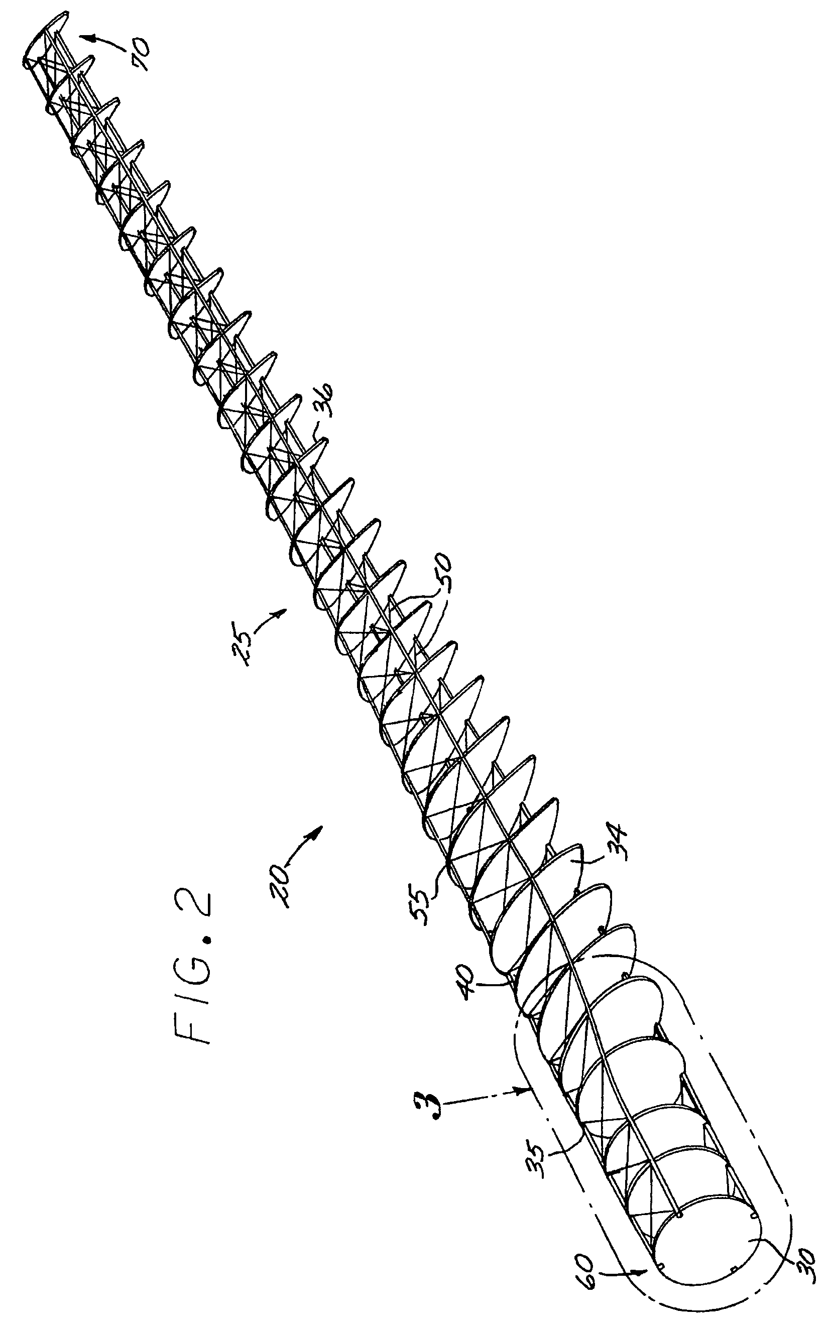
The wind turbine blade described in this patent has a unique internal structure made up of ribs and attachment points. These ribs are connected together by composite spar and cross members, creating a truss support structure. This structure is then covered by an airfoil skin attached to the ribs. The technical effect of this design is a stronger and more efficient wind turbine blade that can withstand higher wind speeds and produce more energy.

Problems solved by technology

However, fossil fuels such as coal and petroleum, previously favored because of their abundance and inexpense are now becoming shunned because of the presumed deleterious effects their consumption has effected on the environment and their increasing costs.
Small individual turbines are used for providing electricity to rural residences or grid-isolated locations because of the current structural capabilities and the economic obstacles associated with generator manufacture and territorial placement.
However, wind power has a high proportion of up-front costs.
These costs are averaged over the projected useful life of the equipment, which can be in excess of twenty years if the generator equipment maintains durability and efficient production.
However, an important turbine siting consideration is access to or proximity to local demand or transmission capacity and such typical sites are distant from local demands; especially those growing demands created by burgeoning communities in flat, low wind-speed areas.
Low wind-speed areas have wind power potential, however, the current technology is considered by some inefficient and / or cost prohibitive for use near to these locales.
This results in a lift force on the blade, which induces a torque about the rotor axis, causing the turbine to rotate.
One obstacle to the development of longer wind turbine blades necessary to increase the disk area and power production is the rapid increase in blade weight as the blade length increases.
The addition of material increases blade material cost, as additional material must be purchased and processed.
Additional weight in a wind turbine blade is detrimental because it increases certain loads on the hub and generator systems due to the increased rotational inertia of the rotor disk, and the increased gravity loads on the blades.
Furthermore, additional weight can be detrimental because it can cause a reduction in the natural vibration frequencies of the blades, potentially causing undesirable interactions with the airstream and / or the dynamics of the tower and support structure.
Furthermore, since the wind speed at a given location varies with time, the use of a larger blade may lower the minimum wind speed at which a turbine can be profitably operated, allowing turbines at a given site to be generating power a larger fraction of the time.
However, wood and canvas materials require a lot of maintenance over their service life.
Also, their shape was associated with a low aerodynamic efficiency creating a relatively high tried for the force they were able to capture.
Furthermore, the weight of steel becomes economically prohibitive in designing longer blades capable of rotating in large arcs within the low-speed wind areas.
While lighter than primarily steel blades, these designs still suffer from the shortcomings associated with the economics of weight per blade unit length of components.
Such solid fiberglass structures are relatively heavy for a 31 meter blade (approximately 12,000 pounds) and require expensive tooling for full-scale heated molds.

Method used


Image

  • Lightweight composite truss wind turbine blade
  • Lightweight composite truss wind turbine blade
  • Lightweight composite truss wind turbine blade

Examples


Embodiment Construction

[0033]There are some landscapes where the windspeed is too low for some wind turbine blades to harvest the surrounding air. In many instances, the blades are unable to harvest the air and rotate about their turbine axis because the blades are too heavy and / or to short to effectively capture relatively low-speed winds. At the heart of some overweight and undersized wind turbine blades is a core support structure that is inefficiently designed to provide weight and low rotational inertia suitable for capturing energy in low wind speed areas. As described herein, Applicants have invented a new wind turbine blade utilizing a core support structure which provides a blade of reduced weight which still meets the structural needs or requirements of a turbine blade.

[0034]As shown in FIG. 1, the wind turbine blade 100 of the subject invention includes a relatively lightweight airfoil that exploits the efficiency of a substantially lightweight composite support truss structure 20 which extends...


PUM

PropertyMeasurementUnit
lengthaaaaaaaaaa
thickaaaaaaaaaa
lengthaaaaaaaaaa

Abstract

A lightweight wind turbine blade formed with a truss support structure assembly of composite truss joints including composite spar and cross members attached to and supporting in spaced relation a spine of lightweight rib panels. The rib panels are oriented in parallel spaced relation from one another and individually molded with perimeters defining individual areas of curvature for the finished blade assembly. The truss support structure is covered with a lightweight fiberglass or hardened fabric skin attached to and fitted on respective rib panel edges forming an airfoil structure.

Description

CROSS-REFERENCES TO RELATED APPLICATIONS[0001]This application claims priority of U.S. Provisional Patent Application Ser. No. 60 / 783,551, filed Mar. 20, 2006.FIELD OF THE INVENTION[0002]The invention relates to airfoil core structures and specifically, wind turbine blades.BACKGROUND OF THE INVENTION[0003]With populations increasing and newly developed communities springing forth in previously uninhabited locales, the demand for power is testing the capacities of energy providers. New sources of fuel or power are being sought daily and sources previously considered inefficient to tap are being studied further to extract whatever power generation may be available. However, fossil fuels such as coal and petroleum, previously favored because of their abundance and inexpense are now becoming shunned because of the presumed deleterious effects their consumption has effected on the environment and their increasing costs. Additionally, there are some that feel the United States has become ...

Claims


Application Information

Patent Timeline
Patent Type & Authority Patents(United States)
IPC IPC(8): B64C11/26
CPCF03D1/0675F03D1/0633F05B2250/71F05B2280/6003F05B2280/6013Y10T29/49332F05C2253/16Y02E10/721F05C2253/04Y02E10/72F05B2240/30
Inventor BAKER, MYLES L.ARENDT, CORY P.
Owner VESTAS WIND SYST AS
Learn More