
Image reading apparatus and image reading module

a reading apparatus and image technology, applied in the field of image reading apparatus, can solve the problems of deteriorating the yield of double side reading, difficult to provide such a plurality of ccd sensors, and long reading time, and achieve the effect of reducing the density difference in read data

Inactive Publication Date: 2009-04-14
FUJIFILM BUSINESS INNOVATION CORP
View PDF15 Cites 18 Cited by
  • Summary
  • Abstract
  • Description
  • Claims
  • Application Information

AI Technical Summary

Benefits of technology

This solution enables consistent image density across both sides of the document, improving reading efficiency and reducing the need for document inversion, thus enhancing the yield of double-side reading while allowing for the use of smaller, more energy-efficient components.

Problems solved by technology

However, in this automatic double side reading by method of front-back inversion, since it is required that the document is inverted after being ejected and conveyed again to the document reading unit, this double side reading takes a long time, and this deteriorates the yield of double side reading.
Particularly, in a case where a plurality of image sensors must be provided for reading both sides of a document without inversion, it is difficult to provide such a plurality of CCD sensors due to limitations of space.
Therefore, when a fluorescent light is used as a light source of one reading unit and an LED is used as a light source of the other reading unit, the difference in emission spectrum between the fluorescent light and the LED poses the following problem when color images formed on both sides of a document are read as monochrome images.
This problem may also occur in cases where the image includes many components of other colors as well as the image including many blue components.

Method used


Image

  • Image reading apparatus and image reading module
  • Image reading apparatus and image reading module
  • Image reading apparatus and image reading module

Examples


Embodiment Construction

[0024]Hereinafter, embodiments of the present invention will be described in detail with reference to the accompanying drawings.

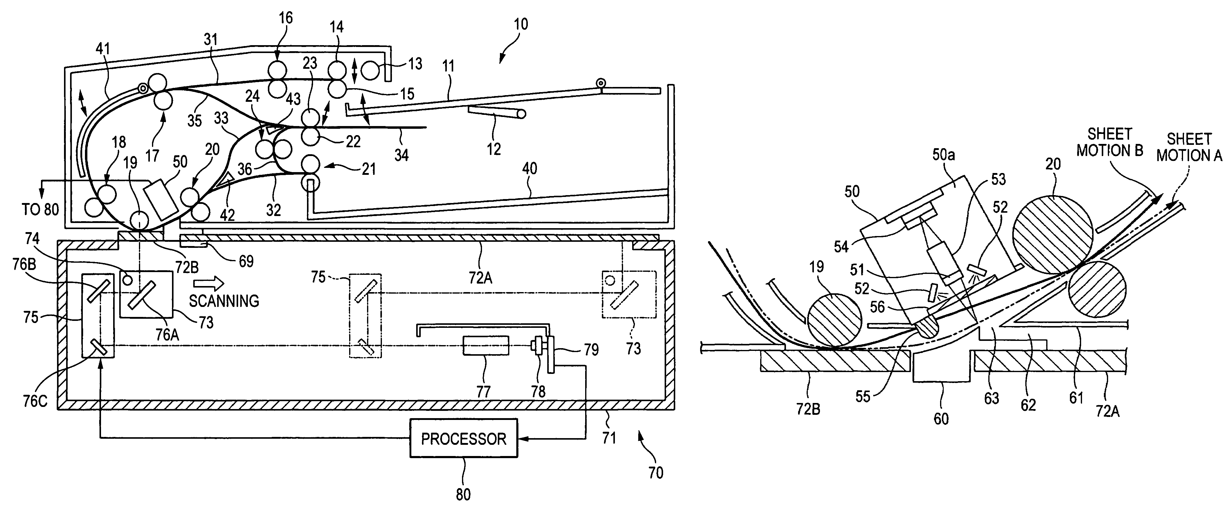
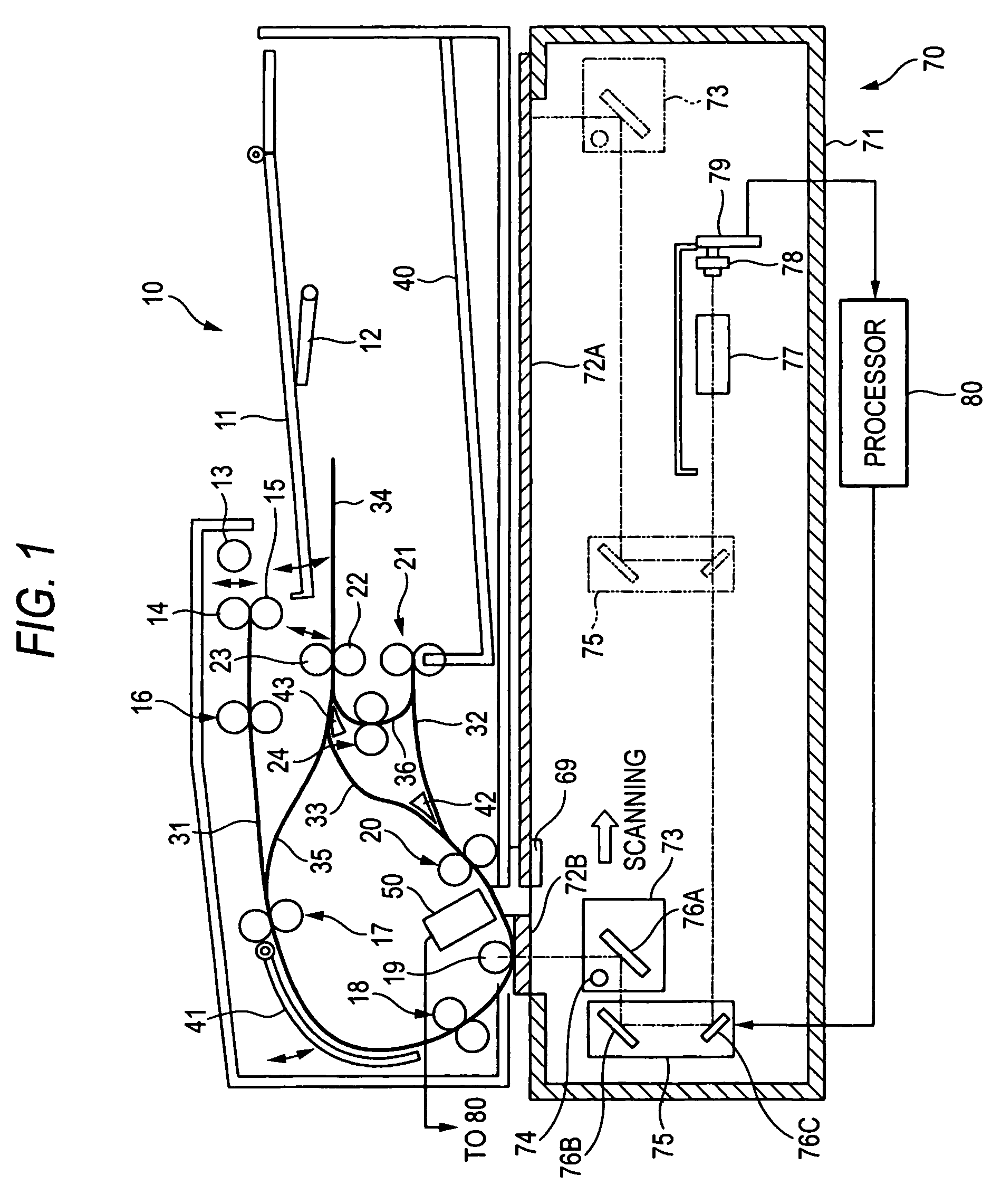
[0025]FIG. 1 is a drawing showing an image reading apparatus applied with this embodiment. This image reading apparatus is mainly divided into a document feeder 10 which conveys documents one by one from a bundle of stacked documents, a scanner 70 which reads-in images by scanning, and a processor 80 which processes read-in image signals.

[0026]The document feeder 10 has a document tray 11 for stacking a bundle of a plurality of documents, and a tray lifter 12 which raises and lowers the document tray 11. The document feeder further has a nudger roll 13 that conveys documents on the document tray 11 raised by the tray lifter 12, a feed roll that further conveys the documents conveyed by the nudger roll 13 to the downstream side, and a retard roll 15 which handles the documents supplied by the nudger roll 13 one by one. The first transfer path 31 to which the...


PUM


Abstract

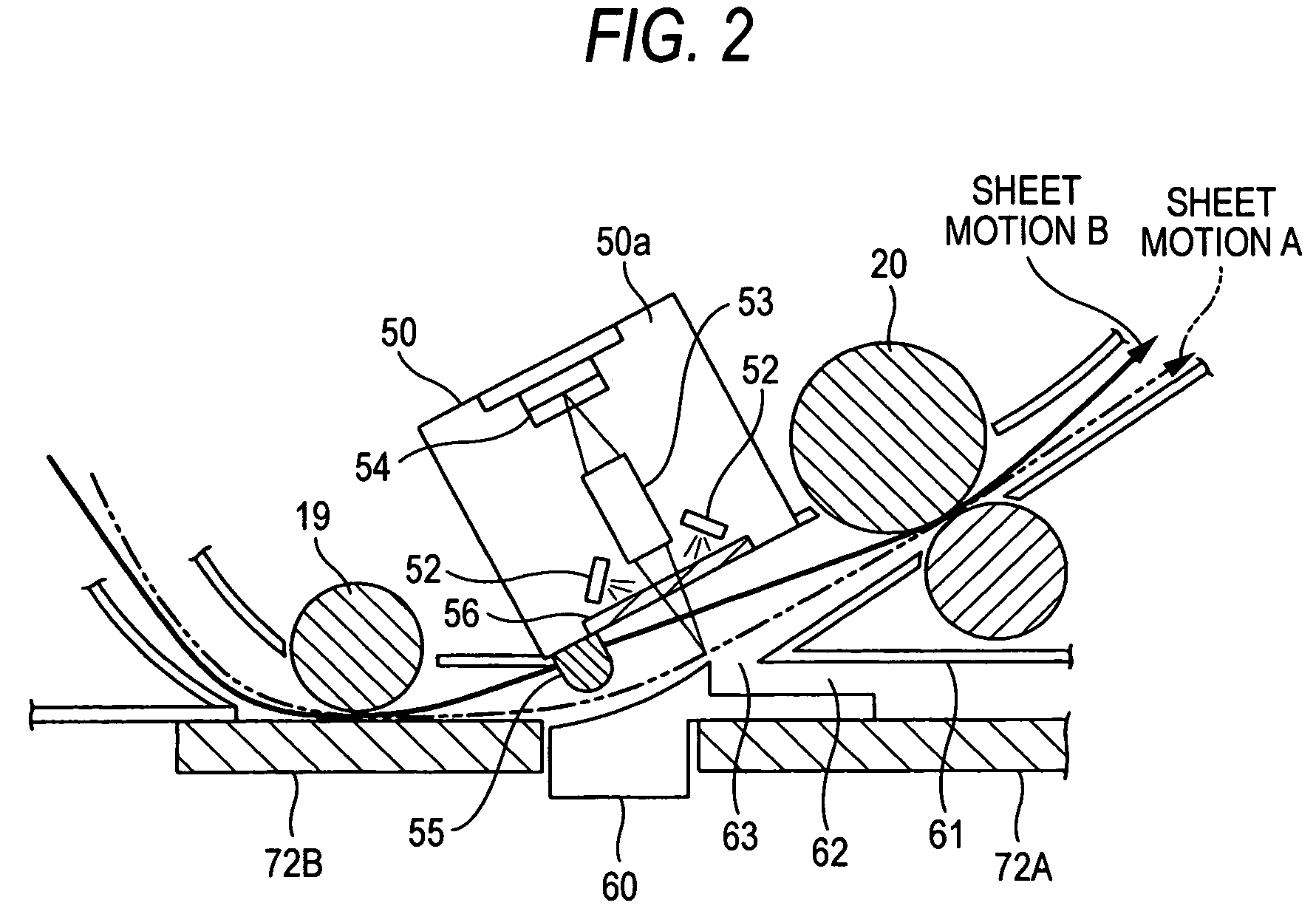
A scanner is provided with an illumination lamp for emitting light to a first side of a document from one side of a transfer path and a CCD image sensor for receiving light reflected from the first side of the document, and a CIS provided in a document feeder is provided with an LED for emitting light to a second side of the document from the other side of the transfer path and a line sensor for receiving light reflected from the second side of the document. The illumination lamp is a xenon lamp, and the LED is a white LED having emission characteristics different from those of the xenon lamp. To the CIS, a filter is attached, which brings emission characteristics of light emitted from the LED onto a document closer to those of light emitted from the illumination lamp onto the document.

Description

BACKGROUND OF THE INVENTION[0001]1. Field of the Invention[0002]The present invention relates to an image reading apparatus which captures images on a document, and more specifically, an image reading apparatus which can capture images on both front and back sides of the document by single transfer.[0003]2. Description of the Related Art[0004]Conventionally, as reading apparatuses such as a copying machine, a facsimile and a scanner for computer inputs, image reading apparatuses (automatic double side reading apparatuses) have been used which automatically read image information on both front and back sides of a document without intervention of users. Among these automatic double side reading apparatuses, a method of reading by inverting the front and back sides of a document at a document inverting unit is widely used. When inputting image information by front-back inversion, after images on the front side are read by a specific document reading unit, this document is inverted and ...

Claims


Application Information

Patent Timeline
Patent Type & Authority Patents(United States)
IPC IPC(8): H04N1/04G03B27/50G03B27/54H04N1/00H04N1/028H04N1/12H04N1/193H04N1/203
CPCH04N1/02815H04N1/02895H04N1/203H04N1/2032H04N1/1215H04N1/193
Inventor SHIRAISHI, RYUUICHIHAMASUNA, SHUNSUKEMIKUNI, YUICHI
Owner FUJIFILM BUSINESS INNOVATION CORP
Learn More