Liquid discharge control apparatus, liquid discharge control method, and liquid discharge control program

a control apparatus and liquid discharge technology, applied in electrical apparatus, printing, pictoral communication, etc., can solve the problem of insufficient reduction of ink ejection amount in the reduction of density change, and achieve the effect of reducing density difference and reducing density difference among printed colors

Active Publication Date: 2017-09-28
SEIKO EPSON CORP
View PDF15 Cites 5 Cited by
  • Summary
  • Abstract
  • Description
  • Claims
  • Application Information

AI Technical Summary

Benefits of technology

[0010]In the above configuration, the color patch printing control unit allows a plurality of color patches targeting predetermined pre-color conversion data and based on a plurality of mutually different color conversion tables to be printed by printing whose execution number of the scan operations is changed. Since the execution number of the scan operations is changed, a density difference resulting from such printing occurs even though predetermined pre-color conversion data is targeted. In contrast thereto, since the mutually different color conversion tables are used, the influence by the configuration in which the execution number of the scan operations is changed is compensated for, and as a result, the reduction of the density difference occurs. After one or more color patches that reduce the density difference have been selected by the selection result acquisition unit, when printing whose execution number of the scan operations corresponds to each of the one or more color patches is performed, the color conversion unit selects a color conversion table having been used in the selection of the each of the one or more color patch, and performs a color conversion using the selected color conversion table.
[0011]Thus, even when printing whose execution number of the scan operations is changed is performed, the above configuration reduces the density differences among printed colors printed by the printing whose execution number of the scan operations is changed.

Problems solved by technology

In the technology disclosed in JP-A-2009-12390, the ink ejection amount is uniformly decreased to reduce the density change that occurs when the pass-to-pass time difference arises, but just the decrease of the ink ejection amount is not sufficient in the reduction of the density change.

Method used


Image

  • Liquid discharge control apparatus, liquid discharge control method, and liquid discharge control program
  • Liquid discharge control apparatus, liquid discharge control method, and liquid discharge control program
  • Liquid discharge control apparatus, liquid discharge control method, and liquid discharge control program

Examples


first embodiment

[0023]Hereinafter, an embodiment according to the invention will be described on the basis of the drawings.

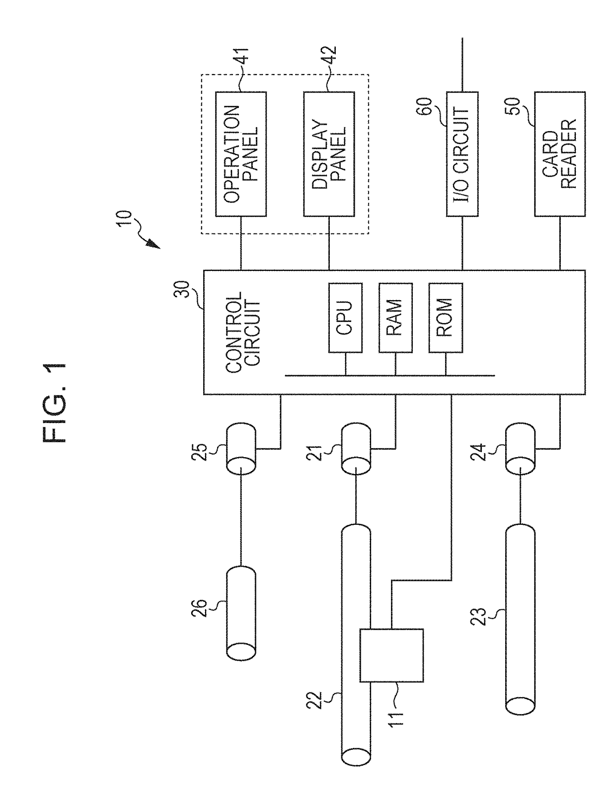
[0024]FIG. 1 illustrates a schematic block diagram of an ink jet printer to which the invention is applied.

[0025]In FIG. 1, a printing head 11 of a printer 10 discharges color inks having four colors or six colors and supplied from an ink tank. The printing head 11 is drivingly reciprocated within a predetermined range by a belt 22. This belt 22 is driven by a carriage motor 21. A platen 23 is driven by a platen motor 24 and transports paper in conjunction with the reciprocation of the printing head 11. A paper feed roller 26 supplies paper contained in a predetermined paper stacker, and a feed motor 25 drives this paper feed roller 26. In this case, paper is one example of the printing medium, and the printing head 11 is linearly driven across the width direction of the printing medium.

[0026]A control circuit 30 is constituted by combining dedicated ICs, and functionally inclu...

second embodiment

[0063]FIG. 8 is a flowchart illustrating processing for setting a color conversion table in a modification example, and FIG. 9 is a diagram illustrating an example of printed color patches.

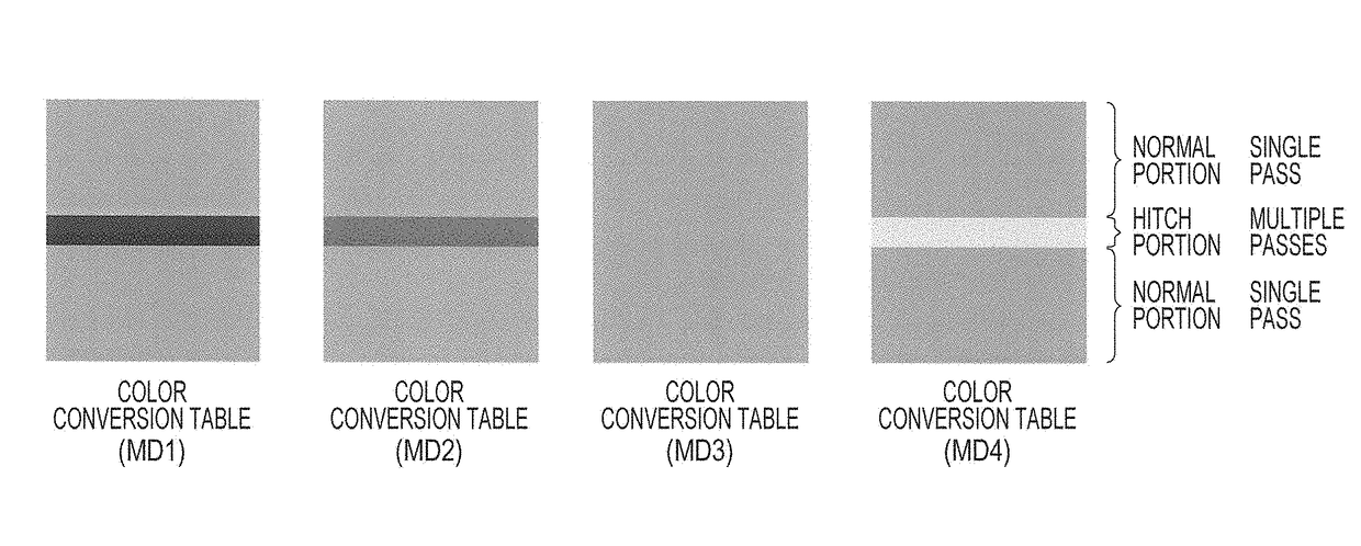
[0064]The CPU included in the control circuit 30 executes a program corresponding to the flowchart shown in FIG. 8. In step S200, the CPU acquires a plurality of color conversion tables. The color conversion LUTs 72, which have been created for the respective media MD1 to MD4, correspond to the above plurality of color conversion tables.

[0065]Each of the color patches shown in FIG. 9 is composed of a normal portion and a hitch portion. In each of the color patches shown in FIG. 7, there is a position relationship in which the hitch portion is sandwiched between the normal portions, whereas, in each of the color patches shown in FIG. 9, the each color patch is printed so as to allow a normal portion and a hitch portion that have approximately the same size to be adjacent to and in contact with each...

third embodiment

[0076]FIG. 10 is a diagram illustrating an example of printed color patches. In each of the color patches shown in each of FIGS. 7 and 9, the normal portion and the hitch portion are printed so as to be adjacent to and in contact with each other. In the color patches shown in FIG. 7, the normal portion and the hitch portion are desirable to be adjacent to and in contact with each other because the density difference is visually recognized by human being. When, however, the scan image data is acquired and the density differences are calculated by making a comparison of the acquired scan image data, it is not necessary to purposely arrange the normal portion and the hitch portion so as to allow the normal portion and the hitch portion to be adjacent to and in contact with each other.

[0077]For this reason, as shown in FIG. 10, color patches for which printing conditions are mutually different are independently printed so as to be distanced from one another. As shown in FIG. 10, when th...


PUM


Abstract

In order to reduce a density difference that appears when printing whose execution number of scan operations is changed is performed, a CPU acquires a plurality of color conversion LUTs; the CPU performs printing of each of normal portions of color patches using a reference LUT and performs printing of each of hitch portions of the color patches using a corresponding one of mutually different color conversion LUTs; the CPU allows a color patch having a small density difference to be input as a selection result; the CPU identifies a color conversion LUT corresponding to the selection result; and the CPU designates the color conversion LUT corresponding to the selection result as a color conversion LUT for the hitch portion.

Description

BACKGROUND[0001]1. Technical Field[0002]The present invention relates to a liquid discharge control apparatus, a liquid discharge control method, and a liquid discharge control program, and in particular, it relates to a liquid discharge control apparatus, a liquid discharge control method, and a liquid discharge control program that allow multi-pass printing to be performed.[0003]2. Related Art[0004]In ink jet printers, printing is performed by allowing a carriage to bidirectionally move an ink head. In this bidirectional printing, a multi-pass printing is sometimes used. In this multi-pass printing, printing is performed by allowing a scan operation to be executed over a printed region a plurality of times.[0005]Heretofore, in the multi-pass printing, after a first printing operation along an outward path, further, a second printing operation along a return path is performed. The time difference of these two printing operations will be referred to as a pass-to-pass time difference...

Claims


Application Information

Patent Timeline
Patent Type & Authority Applications(United States)
IPC IPC(8): B41J2/045
CPCB41J2/04508B41J2/11B41J2/21B41J2/2132H04N1/6033H04N1/6097H04N1/6041
Inventor TAKEUCHI, YASUTOSHIMATSUMURA, TETSUYA
Owner SEIKO EPSON CORP
Why Eureka
Try Eureka