
Optical scanning device and image forming apparatus equipped with the same

a scanning device and image forming technology, applied in the field of optical scanning devices, can solve the problems of inability to correct the curve, the apparatus tends to increase in size, etc., and achieve the effects of reducing the color shift in the color image, reducing the displacement of the image, and ensuring the accuracy of the imag

Active Publication Date: 2009-04-14
KYOCERA DOCUMENT SOLUTIONS INC
View PDF12 Cites 2 Cited by
  • Summary
  • Abstract
  • Description
  • Claims
  • Application Information

AI Technical Summary

Benefits of technology

The invention provides an optical scanning device that can reduce color shifting in images caused by reflecting light beams. The device includes multiple light sources, a deflector, and correction members to correct the light beams. A last reflection member is also included to reflect the corrected light beams to different photoconductors. By configuring the last reflection member with an angle closest to vertical, the reflection surface can have the smallest curve, resulting in a smaller scanning line and less color shifting in the image. This optical scanning device can improve the quality of color images and reduce color shifting caused by the reflecting process.

Problems solved by technology

However, because four optical scanning devices are provided correspondingly to four photoconductive drums to expose the drums, the apparatus tends to increase in size.
However, because the folding mirrors are held at the both end portions alone, they eventually bend due to their own weights and the reflection surfaces are curved.
However, in a case where a curve of different magnitude occurs in the scanning line of each light beam after the light beam passed through the correction lens due to a difference of the angle of installation among the folding mirrors as described above, the curve thus occurred is not corrected and the curved scanning line directly scans the photoconductive drum.
This poses a problem that a color shift resulting from displacement of the scanning line occurs in the formed color image.

Method used


Image

  • Optical scanning device and image forming apparatus equipped with the same
  • Optical scanning device and image forming apparatus equipped with the same
  • Optical scanning device and image forming apparatus equipped with the same

Examples


Embodiment Construction

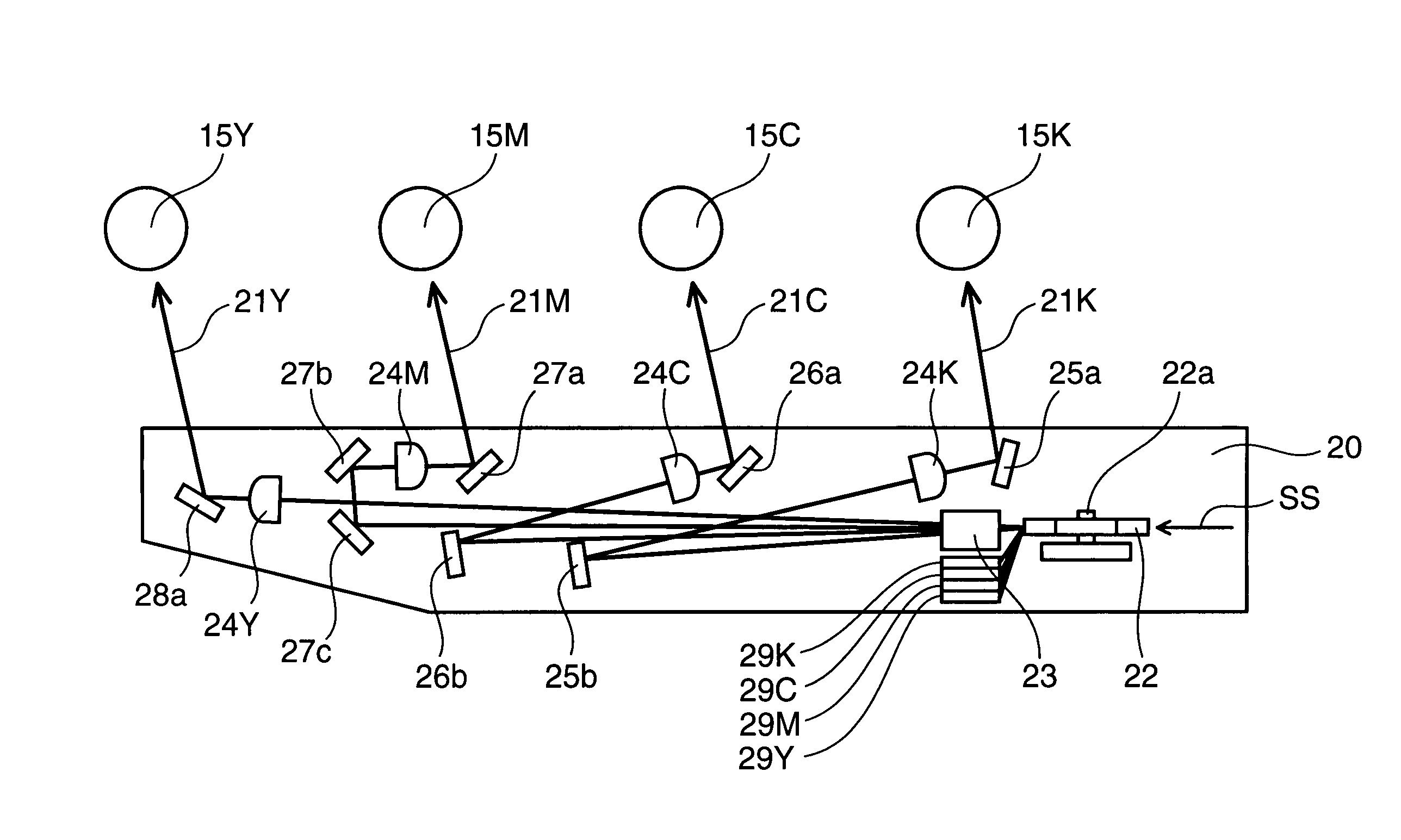
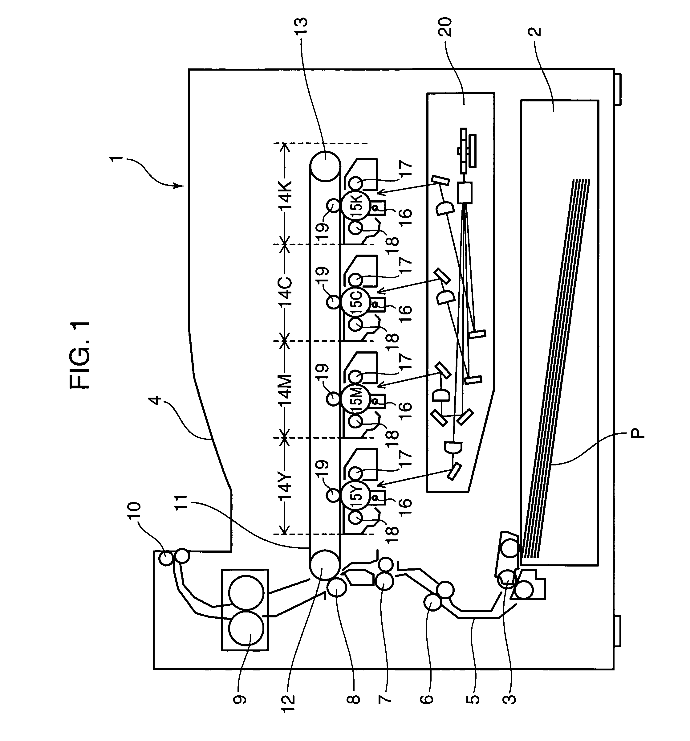
[0017]Hereinafter, an image forming apparatus equipped with an optical scanning device according to one embodiment of the invention will be described with reference to the drawings. FIG. 1 is a view schematically showing the configuration of the image forming apparatus equipped with the optical scanning device according to one embodiment of the invention, and a 4-drum tandem type color image forming apparatus is shown therein.

[0018]A paper feeding portion 2, such as a paper feeding cassette, to store a pile of sheets of paper is provided at the lower portion of the color image forming apparatus 1. A separator feeding member 3 to feed sheets of paper P one by one from the top of the pile is provided at one end portion of the paper feeding portion 2. A paper transportation path 5 extending upward to reach a discharge tray 4 formed on the top surface of the main body is defined above the separator feeding member 3. The separator feeding member 3, a pair of transportation rollers 6, a p...


PUM


Abstract

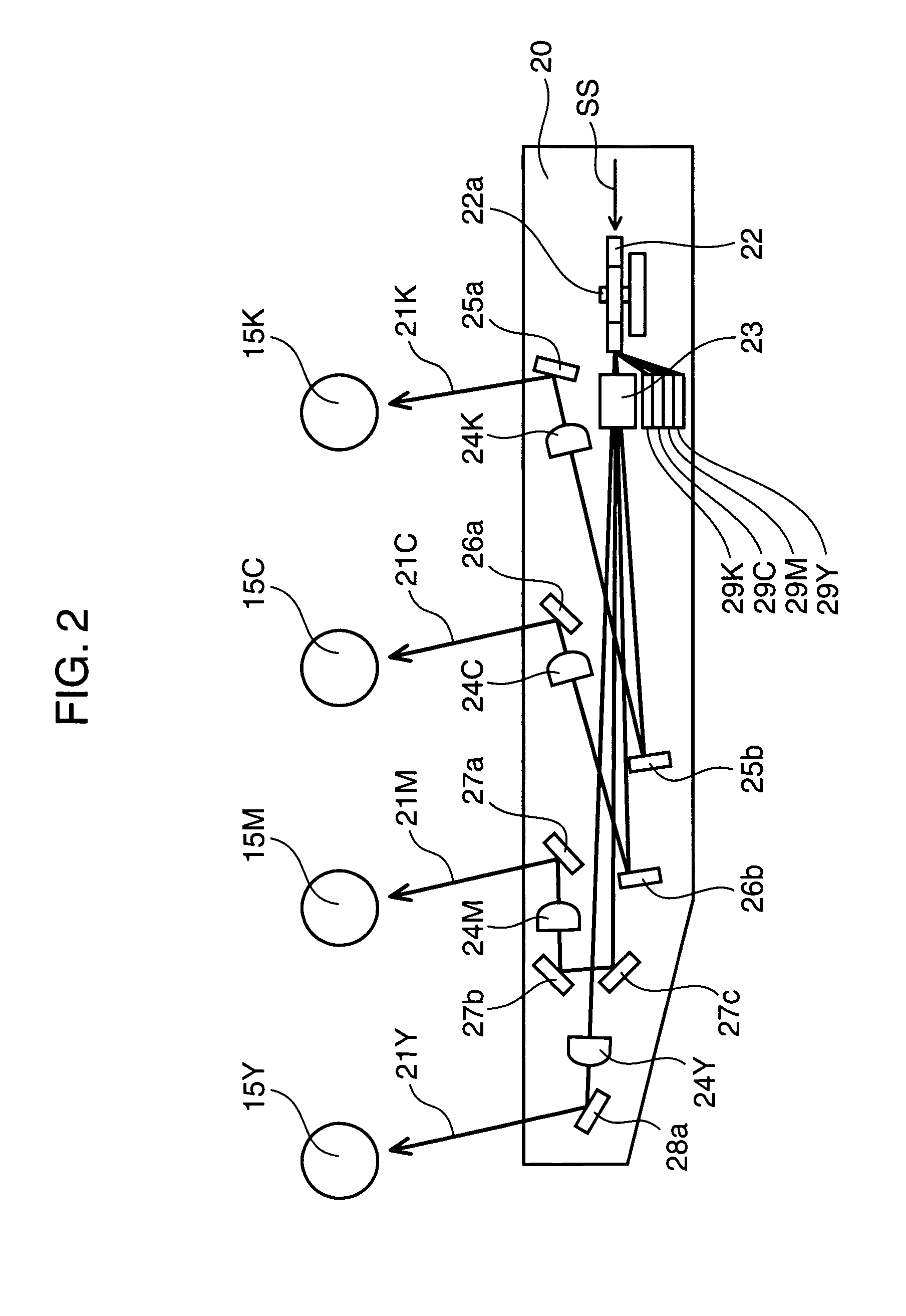
An optical scanning device is configured in such a manner that, of four light beams for colors corresponding to black, cyan, magenta, and yellow, the angle of the reflection surface of the last folding mirror disposed in the optical path of a light beam corresponding to an image in black having the lowest brightness and the highest visibility is closest to vertical, and further, the angle of the reflection surface of the last folding mirror disposed in the optical path of a light beam corresponding to an image in yellow having the highest brightness and the lowest visibility is closest to horizontal. It is thus possible to reduce a color shift in the color image caused by reflecting a light beam having passed through the correction lens on the last folding mirror.

Description

BACKGROUND OF THE INVENTION[0001]1. Field of the Invention[0002]The present invention relates to an optical scanning device that scans light beams to write and form an image for use in an image forming apparatus, such as a printer, a facsimile machine, and a copying machine, and more particularly, to an optical scanning device suitably used in a color image forming apparatus, such as a color laser printer and a digital color copying machine, and an image forming apparatus equipped with the same.[0003]2. Description of the Related Art[0004]An image forming apparatus in the related art using the electrophotographic method, such as a copying machine and a printer, is equipped with an optical scanning device that scans a light beam modulated according to input image data on the surface of a photoconductive drum charged uniformly by the charger. An image is formed by developing an electrostatic latent image formed by the optical scanning device into a toner image by the developing device...

Claims


Application Information

Patent Timeline
Patent Type & Authority Patents(United States)
IPC IPC(8): G02B26/08B41J27/00
CPCG02B26/123G03G15/0409B41J2/473
Inventor KURIHARA, TAKAYUKI
Owner KYOCERA DOCUMENT SOLUTIONS INC
Learn More