Arc discharge protection apparatus operating in current detection mode

a protection apparatus and current detection technology, applied in the direction of emergency protection arrangement details, electrical apparatus, arrangements responsive to excess voltage, etc., can solve the problems of inaccurate control, reduced driving power, and inability to effectively activate the protection mechanism of the transformed lower voltage signal, so as to prevent the mistaken judgment and accurate control

Inactive Publication Date: 2009-04-14
ZIPPY TECH
View PDF2 Cites 6 Cited by
  • Summary
  • Abstract
  • Description
  • Claims
  • Application Information

AI Technical Summary

Benefits of technology

[0003]The primary object of the present invention is to solve the aforesaid disadvantages. The present invention provides an arc discharge protection apparatus operating in current detection mode in response to arc discharge caused by an abnormal condition in a high voltage output zone. The arc discharge protection apparatus includes a current signal sampling unit to receive an arc discharge current signal generated in the high voltage output zone, an interpretation unit to provide a determination level to sift out abnormal current frequency signals, a commutation unit to receive and rectify the abnormal frequency signals and output an arc DC signal, and a touch control unit driven by the arc DC signal to output a trigger signal to stop operation of the high voltage output zone. Thereby sparking or burning caused by heat accumulation of the peripheral elements resulting from arc discharge can be prevented.
[0004]Compared with the conventional voltage detection mode, the current detection mode of the invention has the following advantages:
[0005]1. The voltage detection mode transforms a high voltage signal to a low voltage signal. During the transforming process noise signals often occur and the accuracy is affected. Moreover, driving energy is required by the touch control unit at the rear end. But during transformation of the high voltage to the low voltage in the high voltage output zone, the driving energy of the transformed lower voltage signal cannot effectively activate the protection mechanism (take a backlight module of a display panel as a load for an example, when the required luminance drops 20%, the driving power also decreases). By contrast, as the protection mechanism of the present invention adopts the current detection mode, the current signal does not have much fluctuation during the transformation. Hence the protection mechanism can function more effectively and accurately.
[0006]2. For the voltage protection mode adopted in a circuit in which the load is driven by a push-pull step-up transformer, an abnormal voltage step-up ratio could happen to the dual-step-up transformer (for instance, both might have errors on the resonance frequency, but it is a temporary phenomenon, and not an abnormal condition). The noise signal being generated could be judged mistakenly as an arc noise and result in operation interrupt of the high voltage output zone. By contrast, as the present invention adopts the current detection mode in the protection mechanism, a deviation DC isolating circuit can be included to prevent the mistaken judgement. And a DC comparing level unit can also be included to determine whether the abnormal frequency signal is a single signal or a continuous signal, so that a trigger signal at the rear end can be generated to stop the operation of the high voltage output zone. Thus more accurate control can be achieved.

Problems solved by technology

During the transforming process noise signals often occur and the accuracy is affected.
But during transformation of the high voltage to the low voltage in the high voltage output zone, the driving energy of the transformed lower voltage signal cannot effectively activate the protection mechanism (take a backlight module of a display panel as a load for an example, when the required luminance drops 20%, the driving power also decreases).
The noise signal being generated could be judged mistakenly as an arc noise and result in operation interrupt of the high voltage output zone.

Method used


Image

  • Arc discharge protection apparatus operating in current detection mode
  • Arc discharge protection apparatus operating in current detection mode
  • Arc discharge protection apparatus operating in current detection mode

Examples


Embodiment Construction

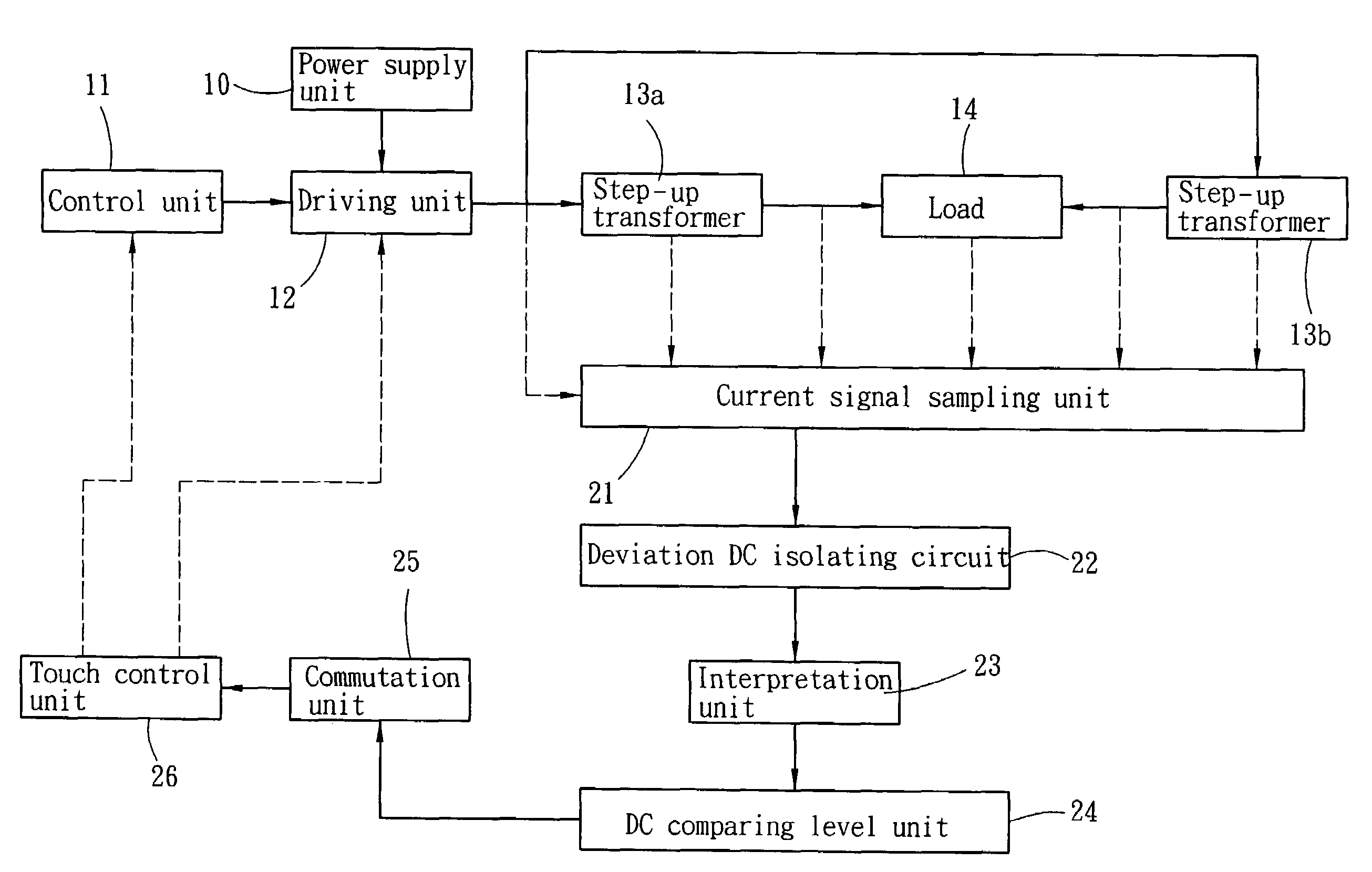
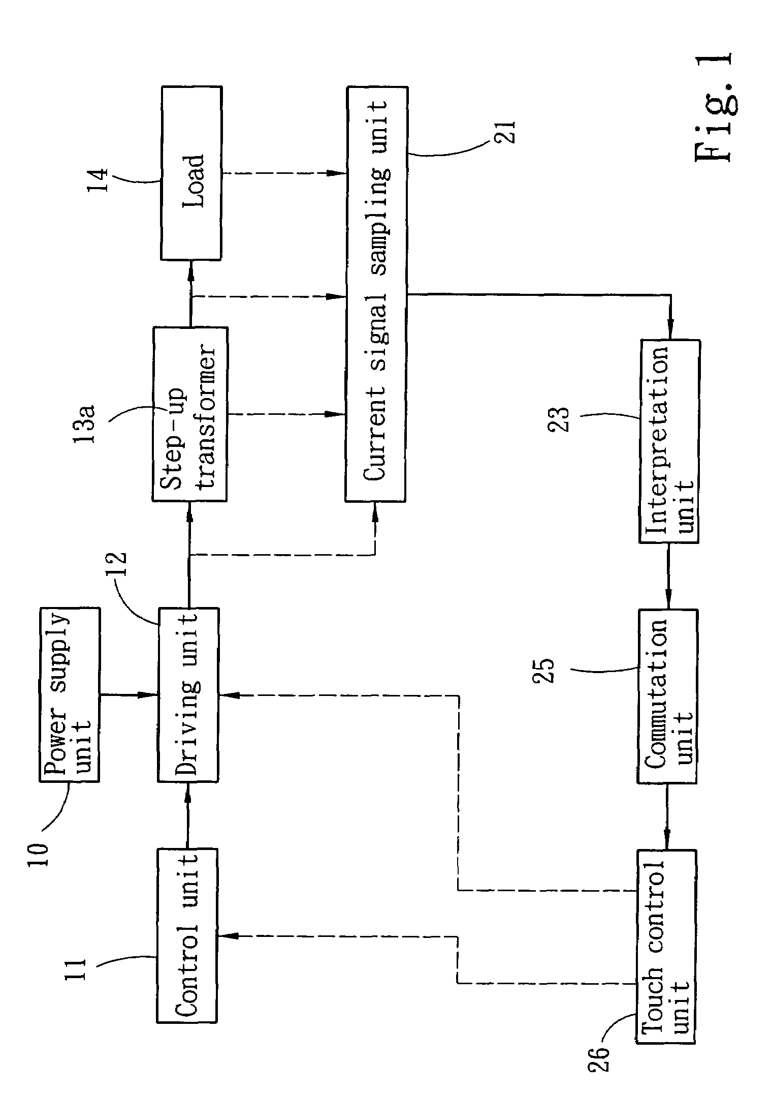
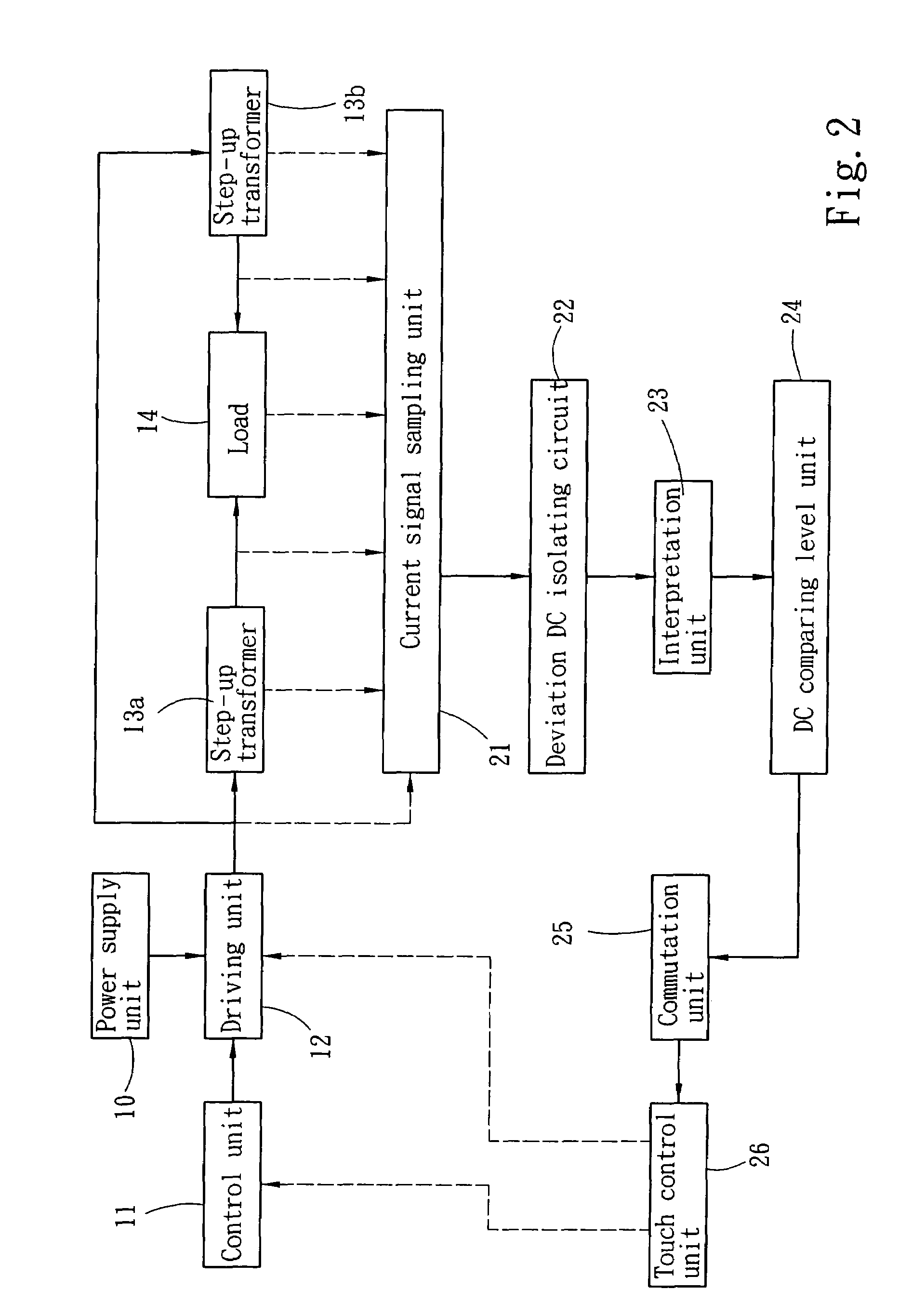
[0011]Please refer to FIG. 1 for the circuit flowchart of a first embodiment of the present invention. The arc discharge protection apparatus operating in current detection mode of the invention aims to prevent arc discharge caused by abnormal conditions in a high voltage output zone. The high voltage output zone includes a power supply unit 10, a control unit 11 to provide voltage distribution signals, a driving unit 12 to receive the power supply and the voltage distribution signals and transform the voltage, a step-up transformer 13a to receive the transformed voltage and transform to a higher voltage, and a load 14 connecting to a higher voltage output end of the step-up transformer 13a (the load 14 is an electronic product driven by the high voltage, such as a cold cathode tube, negative ion generator or the like). (The principle of power supply input, voltage distribution and transformation, and high voltage driving in the high voltage output zone is known in the art, and form...


PUM


Abstract

An arc discharge protection apparatus operating in a current detection mode aims to prevent arc discharge caused by abnormal conditions in a high voltage output zone. The arc discharge protection apparatus has a current signal sampling unit to receive an arc discharge current signal generated in the high voltage output zone, an interpretation unit to provide a determination level to sift out an abnormal current frequency signal, a commutation unit to receive and rectify the abnormal current frequency signal and output an arc DC signal, and a touch control unit driven by the arc DC signal to output a trigger signal to stop operation of the high voltage output zone. Thereby sparking or burning caused by heat accumulation of the peripheral elements resulting from the arc discharge can be prevented.

Description

FIELD OF THE INVENTION[0001]The present invention relates to a protection apparatus to detect arc discharge resulting from an abnormal condition in a high voltage output zone and trigger a control signal to stop high voltage output in the high voltage output zone.BACKGROUND OF THE INVENTION[0002]U.S. Pat. Nos. 6,940,234 and 6,867,955 disclose an arc discharge protection apparatus operating in a voltage detection mode in response to arc discharge caused by an abnormal condition in a high voltage output zone. The protection apparatus includes a voltage transformation unit to receive a high voltage arc discharge signal from the high voltage output zone and transform to a low voltage arc discharge signal, a commutation unit to rectify current and output an arc noise, and a touch control unit to detect the arc noise and output a trigger signal to stop operation of a control unit or a driving unit. Thereby sparking or burning caused by heat accumulation of the peripheral elements resultin...

Claims


Application Information

Patent Timeline
Patent Type & Authority Patents(United States)
IPC IPC(8): H02H3/00H02H3/22
CPCH02H1/0015
Inventor CHOU, CHIN-WENCHENG, YING-NAN
Owner ZIPPY TECH
Why Eureka
Try Eureka