Ball screw assembly

a ball screw and assembly technology, applied in the direction of gearing, gearing elements, hoisting equipments, etc., can solve the problems of increasing production costs, assembly difficulty and interchangeability of fixing parts, conventional ball screws, etc., and never been solved simultaneously

Active Publication Date: 2009-04-21
HIWIN TECH
View PDF6 Cites 4 Cited by
  • Summary
  • Abstract
  • Description
  • Claims
  • Application Information

AI Technical Summary

Benefits of technology

[0009]The primary objective of the present invention is to provide a ball screw assembly, and a method of installing and fixing the circulate component, which is capable of solving the assembly difficulty and the non-interchangeability of the fixing member simultaneously.
[0012]The method of positioning the circulate components in the nut is that: The top portion of the circulate component is formed with a protrusion for engaging with the notch in peripheral edge of the upper portion of the circular hole, so that the circulate component is positioned easily, and the problem of assembly difficulty is solved.
[0013]Regarding the method of fixing the circulate component in the nut, due to the formation of the locking member is determined by the diameter of the hole to be machined, the configuration of locking member will be varied in response to the diameter of the hole to be machined. Whatever the diameter of the hole to be machined changes or not, the interchangeability of the locking member will not be affected. Therefore, the production cost is saved since it doesn't need to prepare different sized locking members.

Problems solved by technology

Therefore, this conventional assembly method is difficult to position the circulate component, making assembly difficult and increasing production cost.
In addition, the method of fixing the conventional circulate member also has its own problem, since the diameter of the fixing holes and the hole through which the nut passes determine the configuration of the fixing member, so if the diameter of the holes changes, the fixing member must be replaced in response to the changed diameter.
Hence, the problems of the conventional ball screw, the assembly difficulty and the interchangeability of the fixing member, have never been solved simultaneously.

Method used


Image

  • Ball screw assembly
  • Ball screw assembly
  • Ball screw assembly

Examples


Embodiment Construction

[0024]The foregoing, and additional objects, features and advantages of the present invention will become apparent from the following detailed description of preferred embodiments thereof, taken in conjunction with the accompanying drawings.

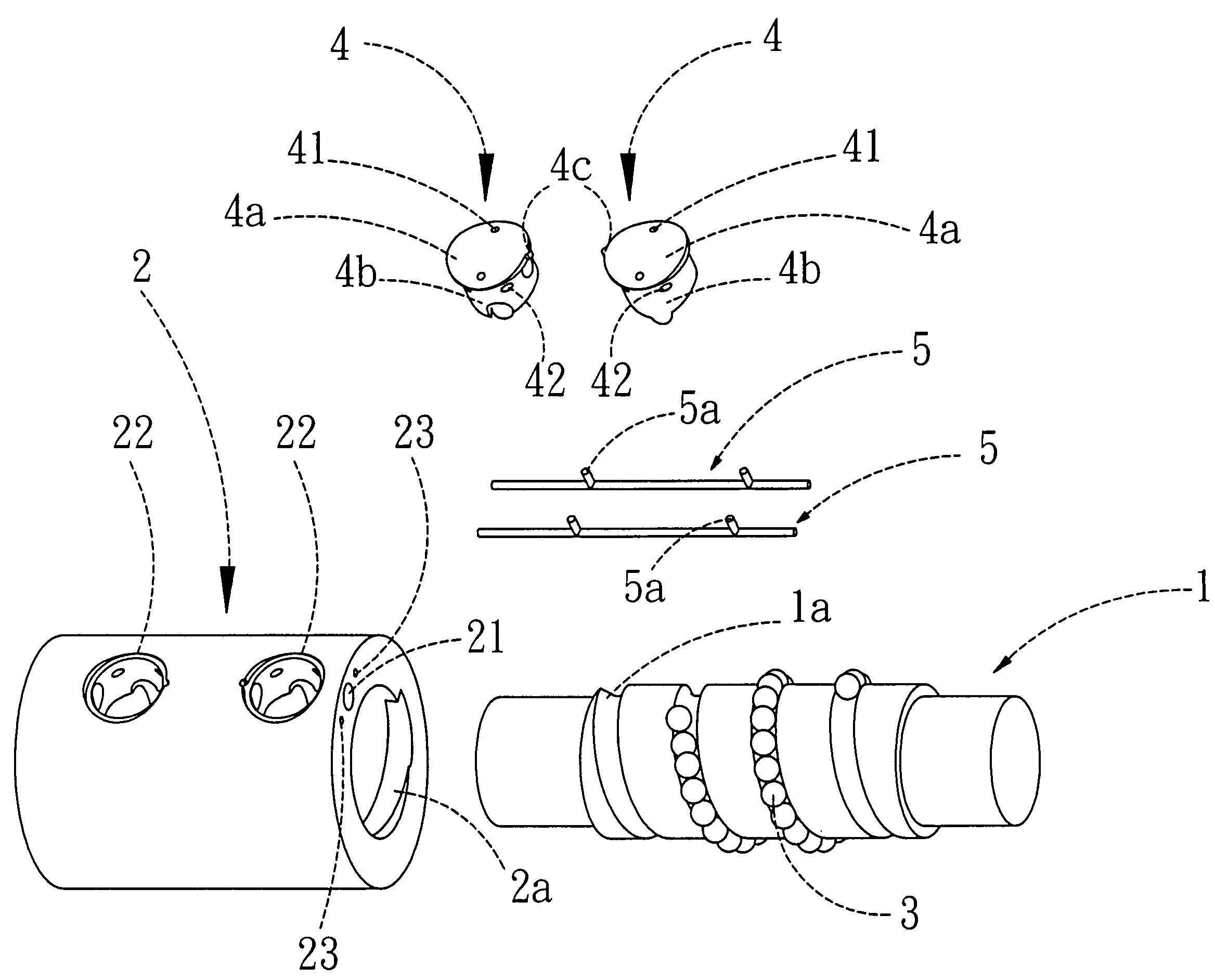
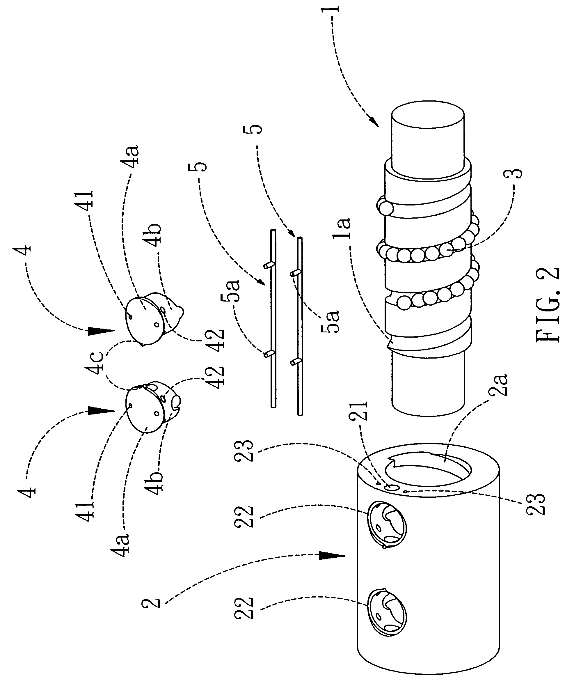
[0025]Referring firstly to FIG. 2, which is an exploded view of a ball screw assembly in accordance with the present invention. The ball screw assembly comprises a screw shaft 1, a nut 2, a plurality of balls 3, two circulate components 4 and two fixing members 5.

[0026]A helical groove 1a is formed in the outer surface of the screw shaft 1 for engaging with the nut 2, two axial locking holes 23 and a circulating hole 21 are formed in an end surface of the nut 2. The nut 2 is hollow, and in its inner surface is formed a helical groove 2a located opposite the helical groove 1a of the screw shaft 1, thus forming a circulating path for the balls 3. The circulate components 4 are disposed in the nut 2 for enabling the balls 3 to roll endlessly in the ...


PUM


Abstract

A ball screw assembly, wherein the circulate component is positioned in the nut by inserting a protrusion in a notch, so that the circulate component is positioned easily, and the problem of assembly difficulty is solved. The method of fixing the circulate components in the nut is that: the circulate component is formed with an axial hole and the radial hole that are connected to each other, the axial hole of the circulate component is aligned to the axial locking hole of the nut, and then liquid resin is injected into the axial hole of the circulate components, and the liquid resin will form a locking members after curing, thus fixing the circulate component in the nut. Due to the formation of the locking member is determined by the diameter of the hole to be machined, the configuration of locking member will be varied in response to the diameter of the hole to be machined. Whatever the diameter of the hole to be machined changes or not, it will not affect the interchangeability of the locking member. Therefore, the production cost is saved since it doesn't need to prepare different sized locking members.

Description

BACKGROUND OF THE INVENTION[0001]1. Field of the Invention[0002]The present invention relates to a ball screw assembly, and more particularly to an improved circulate component fixed in a nut of a ball screw assembly.[0003]2. Description of the Prior Art[0004]Referring to FIG. 1, which is an exploded view of a conventional ball screw, wherein the nut 6 is defined with rectangular recesses 6a for accommodation of the circulate components 7a and 7b. The circulate components 7a and 7b are fixed by screwing fixing members 8 through the fixing hole 7c of the circulate components and into the fixing holes 6b of the nut.[0005]The assembly method of the conventional circulate component is to insert the circulate element directly in the rectangular recess, and the circulate component should be able to move back and forth before it is fixed, that is, the fixing hole in the circulate component must be aligned to the fixing hole of the nut in advance, facilitating the insertion of the fixing me...

Claims


Application Information

Patent Timeline
Patent Type & Authority Patents(United States)
IPC IPC(8): F16H1/24F16H55/02
CPCF16H25/2214Y10T74/19767Y10T74/19772Y10T74/19749
Inventor CHEN, XIN-HE
Owner HIWIN TECH
Why Eureka
Try Eureka