Drilling machine

a drilling machine and drilling technology, applied in the field of drilling machines, can solve the problems of relatively expensive and complicated design of this drilling machine, and achieve the effect of avoiding an overload state of the drilling uni

Active Publication Date: 2009-04-21
C & E FEIN GMBH & CO KG
View PDF25 Cites 11 Cited by
  • Summary
  • Abstract
  • Description
  • Claims
  • Application Information

AI Technical Summary

Benefits of technology

[0008]It is an object of the invention to disclose a drilling machine that can easily avoid an overload state of the drilling unit caused by a too fast feed operation.
[0012]By using a stepper motor an overloading by a too fast feed motion is avoided in a surprisingly simple way. By contrast to a series motor an overload state of the feed motor is not possible, due to its design. By contrast, the feed motion of a stepper motor is limited when reaching a certain resistance so that, as a consequence of which, also the motor of the drilling unit cannot be overloaded by a too fast feed motion.
[0015]By these measures it can be reached that chips generated during metal drilling are broken from time to time and are released from the core drilling bore. In this way the drilling operation is improved and problems and danger caused by sharp-edged chips are avoided.
[0020]In this way the feed motion of the stepper motor can be transferred in a suitable way into a feed operation of the carriage along the stand.
[0023]Thereby it is made possible to allow for a fast manual feed motion of the carriage toward the boring location, in addition to the driving motion generated by the stepper motor. Thereafter, by means of the lever a switching between manual and automatic feed motion generated by the stepper motor can be affected by axially displacing the plunger.
[0031]Thereby an improved adaptation of the drilling tool rate to various operating conditions is made possible.

Problems solved by technology

By using such a control an overload state can be avoided, however the design is relatively costly and complicated.
Also the design of this drilling machine is relatively costly and complicated.

Method used


Image

  • Drilling machine
  • Drilling machine
  • Drilling machine

Examples


Embodiment Construction

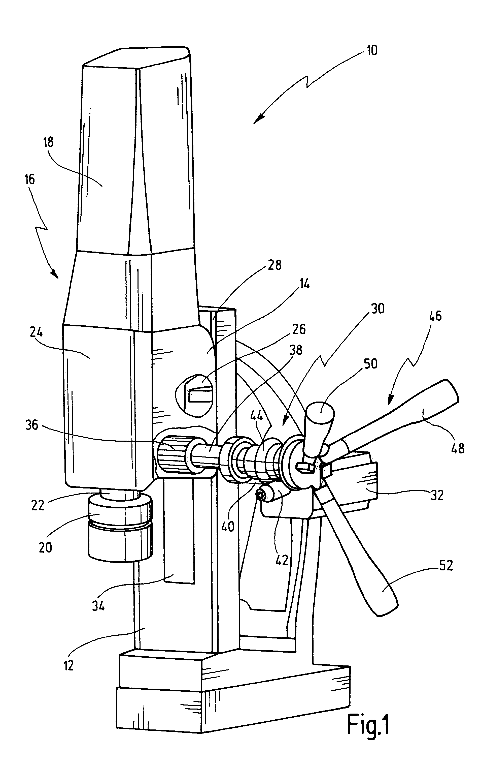
[0038]In FIG. 1 a drilling machine according to the invention is depicted in general with numeral 10.

[0039]The drilling machine 10 according to the invention is configured as a core drilling machine comprising a stand 12, wherein a drilling unit 16 is received on a carriage 14 which can be moved by means of a drive 30 along a guide 28.

[0040]The drilling unit 16 comprises a motor 18 designed as a universal motor which drives a spindle 22 for driving a drilling tool 20 by means of a three-speed gear 24. To adjust the different gear ratios, a selecting lever 26 is received rotatably on the housing of the drilling unit 16.

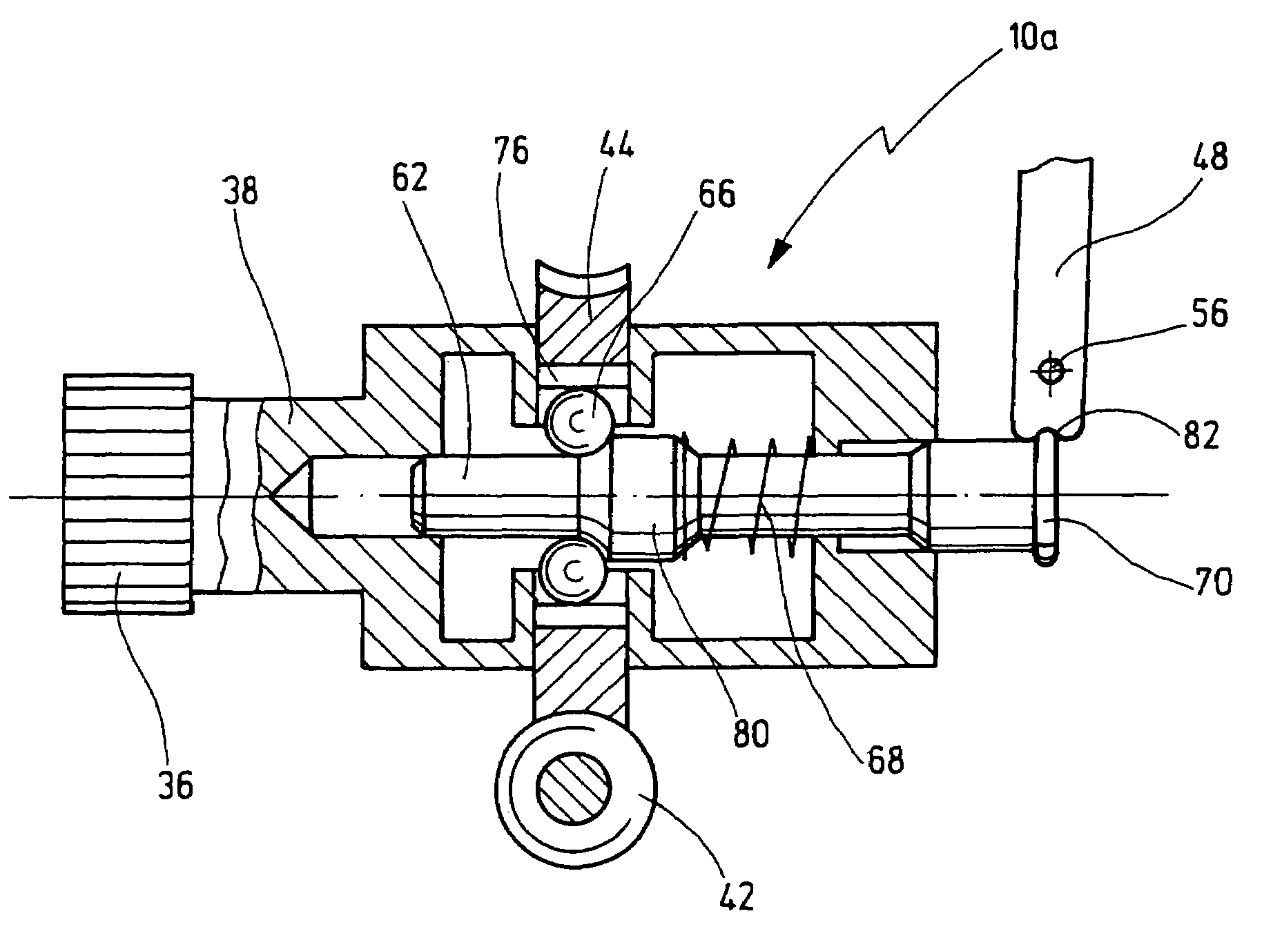
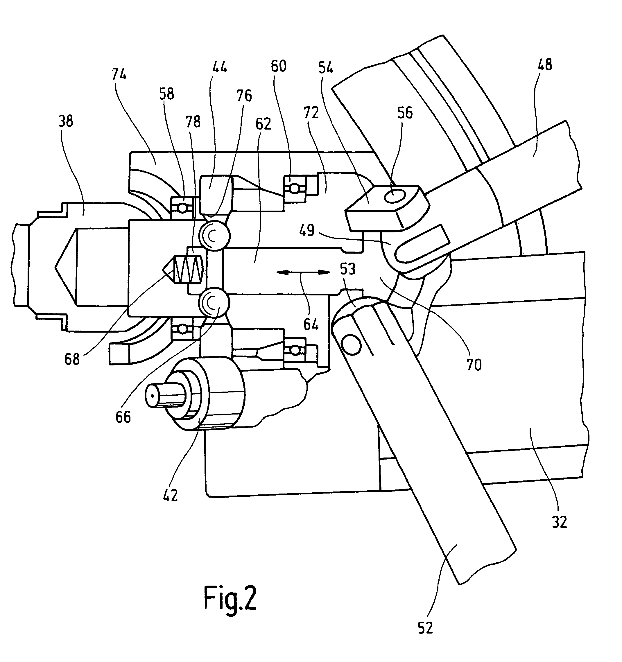
[0041]For feeding the drilling unit 16 or the carriage 14, respectively, on the carriage 14 a tooth rod 34 is received which can be driven by means of a pinion 36 received rotatably on the stand 12, as will be explained in detail hereinafter.

[0042]The pinion 36 can either be automatically driven by a drive 30 comprising a stepper motor 32, or can be manually driven by ...


PUM

PropertyMeasurementUnit
current levelaaaaaaaaaa
resistanceaaaaaaaaaa
pressureaaaaaaaaaa

Abstract

A drilling machine comprises a stand on which a carriage is guided and can be moved by a drive supported on the stand and engagable with the carriage for generating feed motion of the carriage along the guide. A drilling unit on the carriage includes a motor-driven spindle. An axially-fixed intermediate shaft on the stand engages the carriage and translates rotary motion of the intermediate shaft into linear motion of the carriage along the guide. The drive is engagable with the intermediate shaft for moving the carriage along the guide with a stepper motor. A lever is engagable with an axially-displaceable plunger for shifting the plunger between first and second positions corresponding to an engaged position and a disengaged position, in which the plunger allows for manual rotation of the intermediate shaft when rotating the lever.

Description

[0001]This application claims priority from German Patent Application No. 10 2004 033 361.0 filed on Jul. 2, 2004.BACKGROUND OF THE INVENTION[0002]The invention is directed to a drilling machine, in particular a core drilling machine, comprising a stand, whereon a carriage is guided, the carriage being movable along a guide by means of a drive in a working direction, wherein on the carriage a drilling unit is supported that comprises a spindle being driven by a motor for driving a drilling tool.[0003]From German patent application DE 4 019 515 A1 a magnetic stand drilling unit is known which comprises a frame and a magnetic stand which attaches magnetically to a drilling work piece, further comprising an electric drilling machine having a motor and a feed motor designed as a DC motor being supported on the frame for feeding the drill toward the work piece and for returning there from, wherein a control is provided comprising a sensing means for sensing the completion of a bore drill...

Claims


Application Information

Patent Timeline
Patent Type & Authority Patents(United States)
IPC IPC(8): B23B47/18
CPCB23B39/00B23Q5/36B23Q11/04B25H1/0071B25H1/0064Y10T408/6771Y10T408/6786
Inventor WIEHLER, JUERGENBORTZ, JOERGSCHELLHAMMER, KURTBEICHERT, MARTIN
Owner C & E FEIN GMBH & CO KG
Why Eureka
Try Eureka