
Self expanding bifurcated endovascular prosthesis

a prosthesis and bifurcation technology, applied in the field of endoluminal repair of a vessel, can solve the problems of proximal leakage, many failures, and prosthesis that does not have internal support, and achieve the effect of reducing the cross-section

Inactive Publication Date: 2009-04-21
ENDOLOGIX LLC
View PDF167 Cites 77 Cited by
  • Summary
  • Abstract
  • Description
  • Claims
  • Application Information

AI Technical Summary

Problems solved by technology

These straight tube grafts were at first unsupported meaning that they employed stents at their proximal and distal ends to anchor the proximal and distal ends of the graft to the healthy portions of the aorta thereby leaving a midsection of the graft or prosthesis that did not have any internal support.
Although this type of graft at first appeared to correct the aortic aneurysm, it met with many failures.
The unsupported nature of its midsection allowed the graft to migrate distally as well as exhibit significant proximal leakage due to the enlargement of the aorta without adaptation of the graft, such as enlargement of the graft, to accommodate the change in diameter of the aorta.
These types of grafts are complex to deploy and have the potential for leakage at the connection site of the two limbs of the graft.
Although all of the above-described one piece bifurcated grafts have eliminated the problems of leakage and graft failure at the suture or juncture site associated with two piece bifurcated grafts which join together two separate grafts to form the bifurcated graft, problems still exist with these one piece bifurcated grafts.
Further, the same problems with graft migration that existed with straight tube grafts still exist with the one piece bifurcated grafts.
The previously described deployment methods, systems and devices do not allow for a bifurcated graft which is fully supported with self-expandable stents to be delivered and implanted within an arterial bifurcation.
A use of any of the previously described deployment devices or systems to implant the structural supported bifurcated graft of the present invention would result in failure due to the inability of those devices and systems to deliver and anchor the second supported limb within the second iliac artery.
The previously described methods and systems simply do not allow for the delivery and implantation of a bifurcated vascular graft whose three open ends are supported by stents.

Method used


Image

  • Self expanding bifurcated endovascular prosthesis
  • Self expanding bifurcated endovascular prosthesis
  • Self expanding bifurcated endovascular prosthesis

Examples


Embodiment Construction

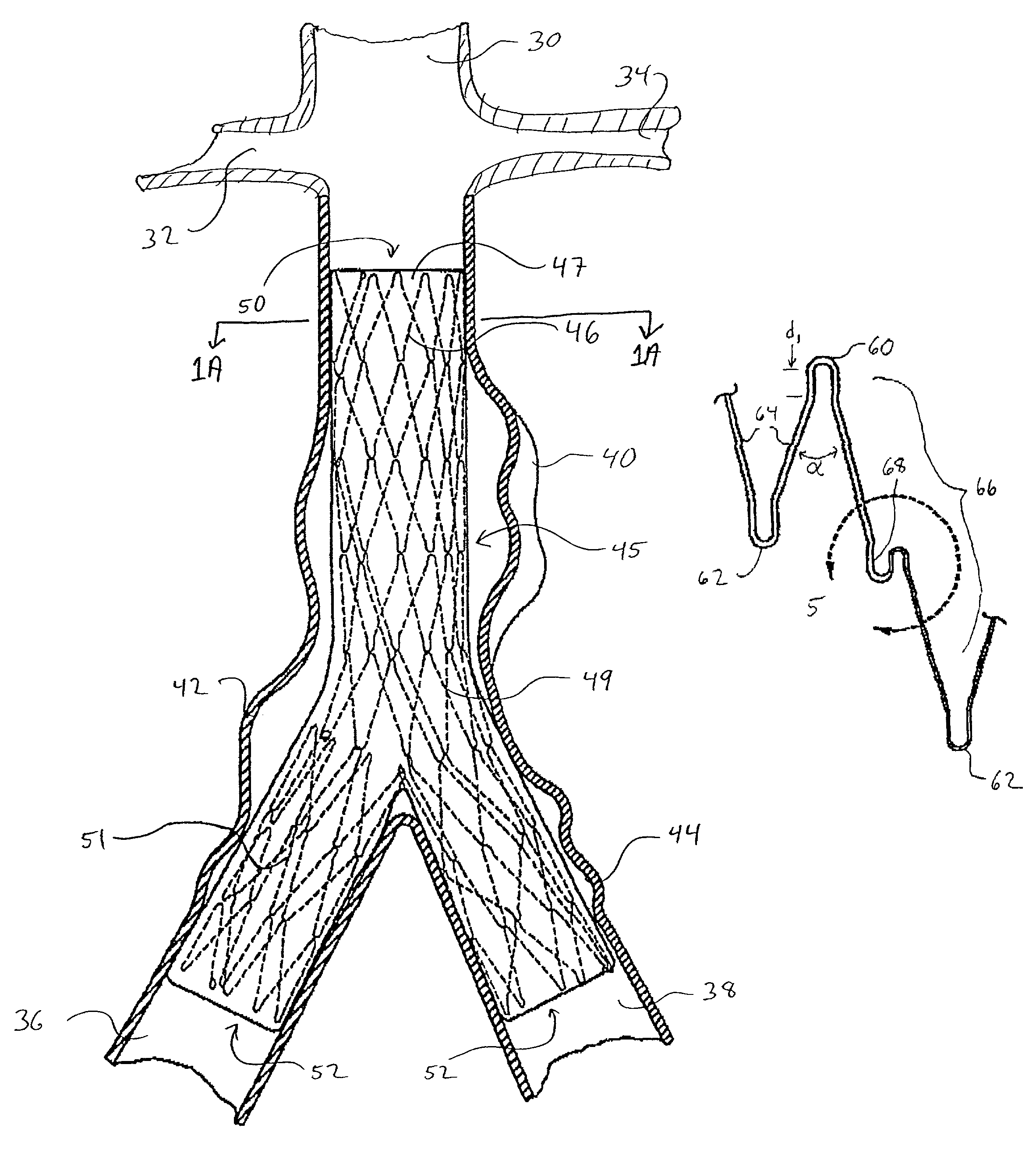
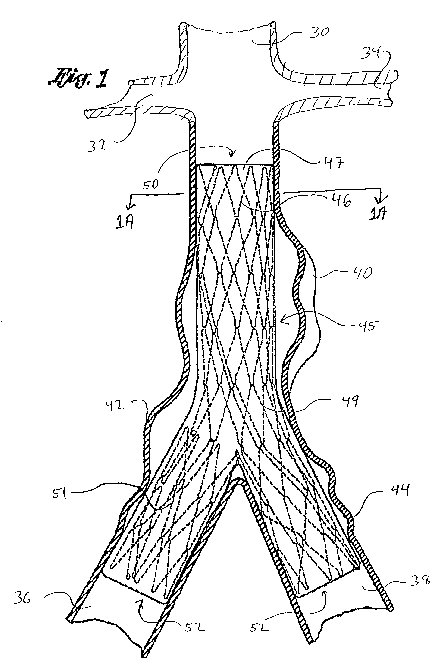
[0058]Referring to FIG. 1, there is disclosed a schematic representation of the abdominal part of the aorta and its principal branches. In particular, the abdominal aorta 30 is characterized by a right renal artery 32 and left renal artery 34. The large terminal branches of the aorta are the right and left common iliac arteries 36 and 38. Additional vessels (e.g., second lumbar, testicular, inferior mesenteric, middle sacral) have been omitted for simplification. An abdominal aortic aneurysm 40 is illustrated in the infrarenal portion of the diseased aorta. Portions of the same aneurysm 40 or additional aneurysms extend into a bifurcation region 42 and an iliac region 44 of the left common iliac 38.

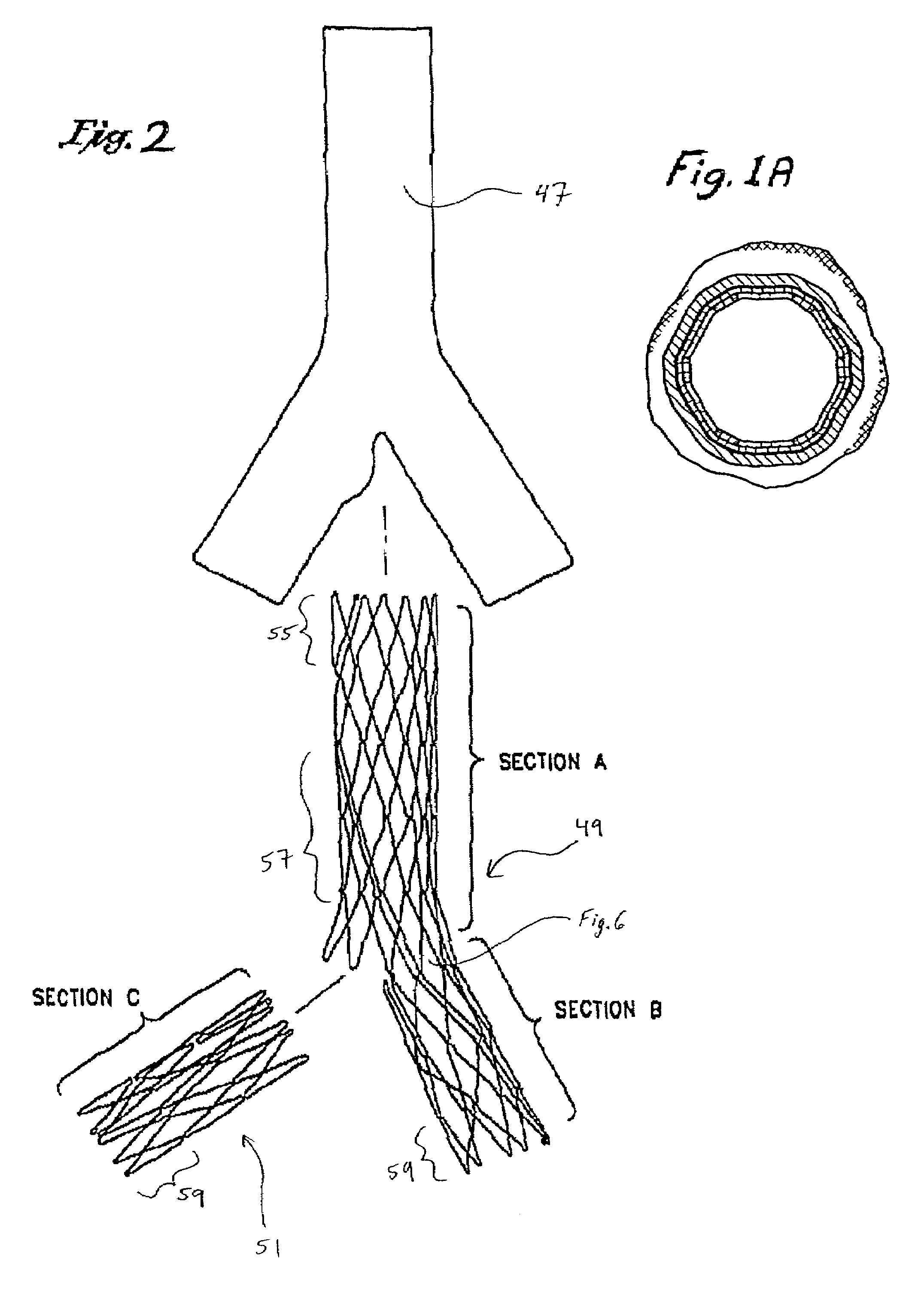
[0059]An expanded endoluminal vascular prosthesis 45, in accordance with the present invention, is illustrated spanning the aneurysms 40, 42 and 44. The endoluminal vascular prosthesis 45 includes a polymeric sleeve 47 and a tubular wire support 46, which are illustrated in situ in FIG. 1...


PUM


Abstract

Disclosed is a bifurcated tubular endoluminal vascular prosthesis, useful in treating, for example, an abdominal aortic aneurysm. The prosthesis comprises a self expandable wire support structure surrounded at least in part by a flexible tubular membrane. A delivery catheter and methods are also disclosed.

Description

BACKGROUND OF THE INVENTION[0001]The present invention relates to endoluminal repair of a vessel, and, in particular, repair of a bifurcation aneurysm such as at the iliac bifurcation of the abdominal aorta.[0002]Endoluminal repair or exclusion of aortic aneurysms has been performed for the past several years. The goal of endoluminal aortic aneurysm exclusion has been to correct this life threatening disease in a minimally invasive manner in order to effectuate a patient's quick and complete recovery. Various vascular grafts exist in the prior art which have been used to exclude aortic aneurysms. These prior art grafts have met varying degrees of success.[0003]Initially, straight tube grafts were used in the infrarenal abdominal aorta to exclude the aneurysmal sac from the blood stream thereby resulting in the weakened aortic wall being protected by the graft material. These straight tube grafts were at first unsupported meaning that they employed stents at their proximal and distal...

Claims


Application Information

Patent Timeline
Patent Type & Authority Patents(United States)
IPC IPC(8): A61F2/06
CPCA61F2/07A61F2/954A61F2/91A61F2/958A61F2002/065A61F2002/075A61F2/89A61F2/90A61F2220/0058A61F2220/0075
Inventor DOUGLAS, MYLES S.MADRID, GILBERTSHOKOOHI, MEHRDAD M.
Owner ENDOLOGIX LLC
Learn More