Method and apparatus for image processing based on a mapping function

a mapping function and image processing technology, applied in the field of methods, can solve the problems of color constancy, system deficiency in reproducing images with the same level of detail, and substantial difference between how an image is perceived by a person and an image captured and reproduced on a display medium,

Inactive Publication Date: 2009-04-21
SAMSUNG ELECTRONICS CO LTD
View PDF6 Cites 11 Cited by
  • Summary
  • Abstract
  • Description
  • Claims
  • Application Information

AI Technical Summary

Benefits of technology

[0009]In another embodiment, the present invention provides an example image processing method based on retinex theory, with at least the following differences compared with the conventional retinex-based algorithms: 1) the example method operates only on a luminance channel while the conventional methods operate on three different color channels, 2) the example method does not cause shading effect; 3) the example method does not cause color distortion; and 4) the example method utilizes a tone mapping function which maintains the intensity value of input data to the intensity value of output data, whereas conventional retinex methods map the input intensity values to different output values according to local and global information of the input data.

Problems solved by technology

There remains, however, a substantial difference between how an image is perceived by a person and an image captured and reproduced on a display medium.
Despite the improvements gained by conventional digital image processing systems, such systems are still deficient in reproducing an image with the same level of detail, color constancy, and lightness of an actual scene as the eye, brain, and nervous system of a human being.
Each have their respective limitations however.
One problem associated with these non-linear systems is that they provide greater distinctions between pixels regardless of what lightness value a pixel may have been originally assigned.
This results in the brighter areas which already have a “washedout” appearance to become even more washed-out.
Although these techniques result in better details in the darker regions, they do so at the expense of the brighter areas of the digital image.
Further, these methods cannot handle contours and abrupt boundaries well.
However, such techniques are unsatisfactory for a number of reasons.
In another technique a shift in color occurs in some images (i.e., color distortion) and is computationally intensive.

Method used


Image

  • Method and apparatus for image processing based on a mapping function
  • Method and apparatus for image processing based on a mapping function
  • Method and apparatus for image processing based on a mapping function

Examples


Embodiment Construction

[0014]A example method and apparatus of improving details in a digital image according to an embodiment of the present invention is described. Accordingly, details for a digital image are enhanced while brightness and color constancy are preserved. At a given point (e.g., pixel) in the image, a determination is made as to whether the pixel “path elements” constituting a path are brighter or darker than the point. The output of the given point is adjusted to generate an enhanced value from averaging the outputs of path-computations selected against the given point.

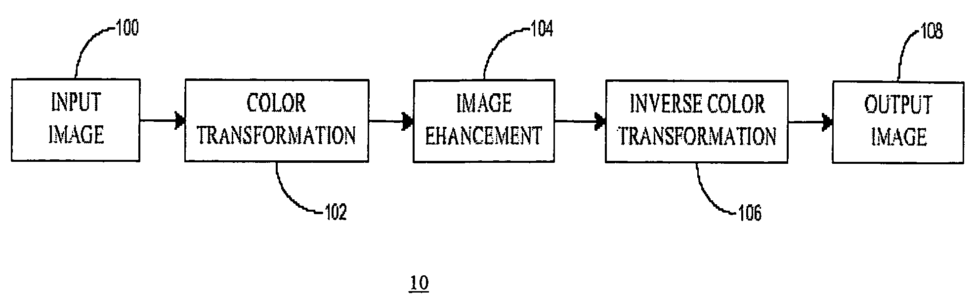
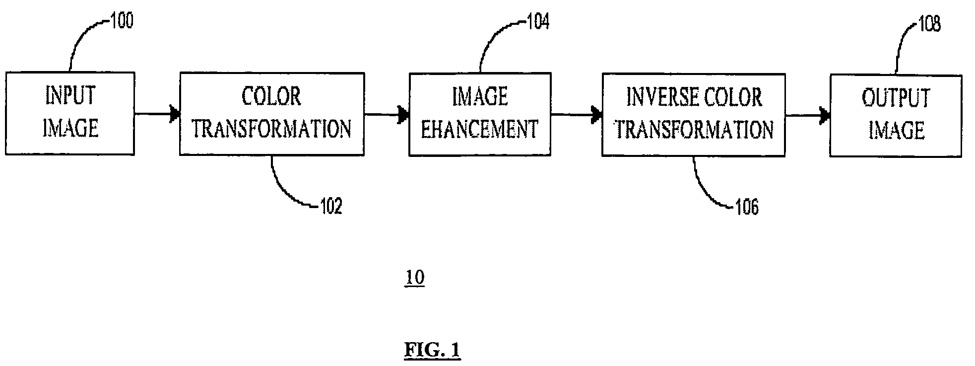
[0015]FIG. 1 shows a block diagram of an image processing system 10 according to an embodiment of the present invention. An image is captured and digitized in block 100 according to well-known techniques, wherein the digitized image is represented by discrete areas referred to as pixels. In one example, the digitized image comprises three color channels, which are Red, Green, and Blue channels (also known as RGB). The color...


PUM


Abstract

A method for processing a digital input image data indexed to represent positions on a display such that the digital data is indicative of an intensity value for each position. The intensity value for each position is transformed to generate an enhanced value, using a mapping function which transforms the same intensity value of input data to essentially the same intensity value of output data in the luminance channel.

Description

FIELD OF THE INVENTION[0001]The present invention relates generally to image processing, and more particularly to a method and apparatus for increasing details in dark regions of an image while maintaining brightness and color constancy.BACKGROUND OF THE INVENTION[0002]Image processing systems are at the heart of digital image revolution. These systems process the captured digital image to enhance the clarity and details of the image using image processing algorithms. Such algorithms result in images that are substantially more accurate and detailed than previously achieved using older analog methods.[0003]There remains, however, a substantial difference between how an image is perceived by a person and an image captured and reproduced on a display medium. Despite the improvements gained by conventional digital image processing systems, such systems are still deficient in reproducing an image with the same level of detail, color constancy, and lightness of an actual scene as the eye...

Claims


Application Information

Patent Timeline
Patent Type & Authority Patents(United States)
IPC IPC(8): G06K9/00G06K9/40H04N1/40
CPCG06T5/007H04N9/64G06T5/00
Inventor LEE, SANGKEUNKIM, YEONG-TAEG
Owner SAMSUNG ELECTRONICS CO LTD
Why Eureka
Try Eureka