System and shadow bistable circuits coupled to output joining circuit
What is Al technical title?
Al technical title is built by PatSnap Al team. It summarizes the technical point description of the patent document.
a shadow bistable, output joining circuit technology, applied in the field of electronic devices, can solve problems such as system-level soft error rate, digital system also may be susceptible to single event transients (sets), and may be significant soft errors
Inactive Publication Date: 2009-04-21
INTEL CORP
View PDF11 Cites 12 Cited by
Summary
Abstract
Description
Claims
Application Information
AI Technical Summary
This helps you quickly interpret patents by identifying the three key elements:
Problems solved by technology
Method used
Benefits of technology
Problems solved by technology
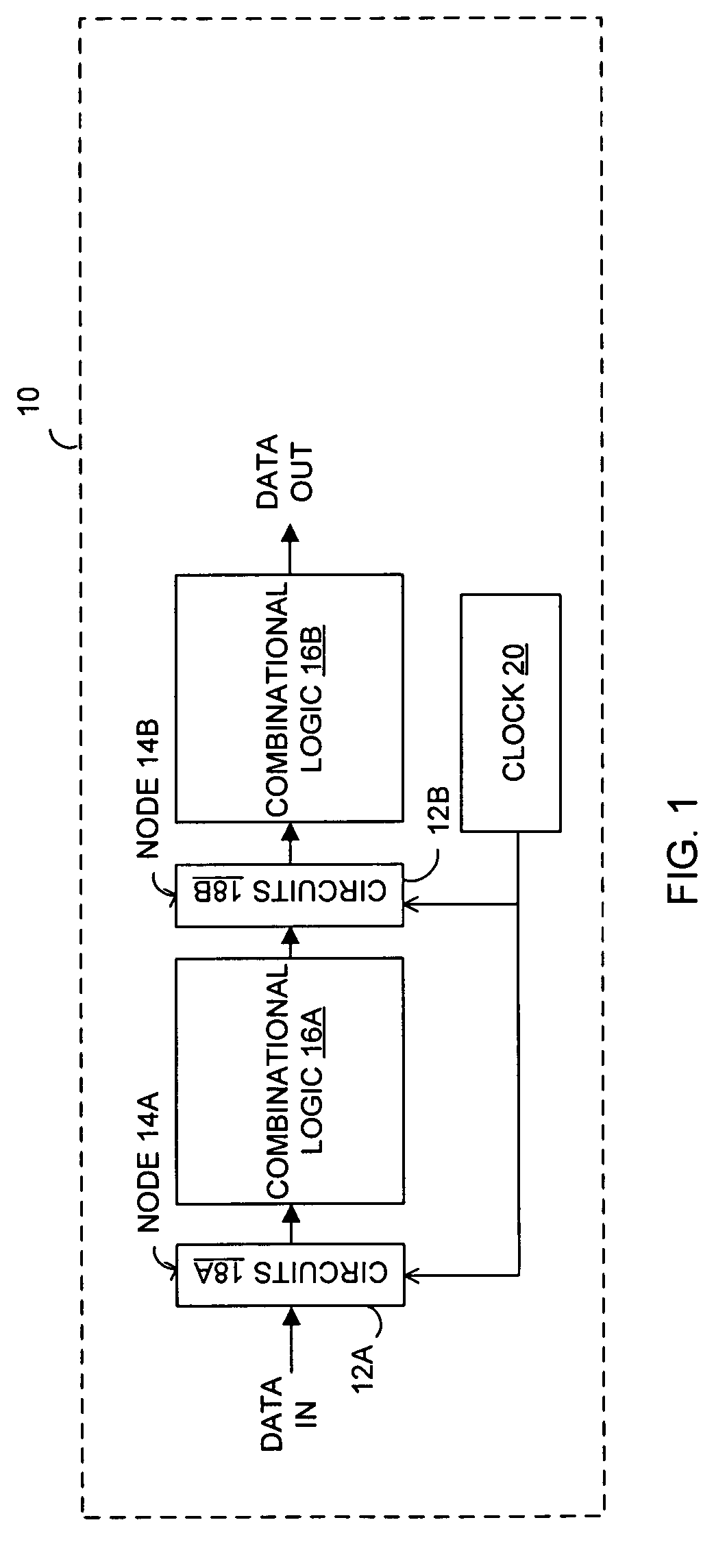
Soft errors may be significant for microprocessors, network processors, high end routers and network storage components that target enterprise and applications where high reliability, data integrity and availability are desirable.
Sequential circuits, such as bistable circuits (e.g., latches and flip-flops), may be major contributors to the system-level soft error rate.
In addition to soft errors in bistable circuits, the digital systems also may be susceptible to single event transients (SETs), which are soft errors originating in combinational logic circuits that drive the latches and flip-flops.
Method used
Image
Click on the blue label to locate the original text in one second.
Reading with bidirectional positioning of images and text.
Examples
Embodiment Construction
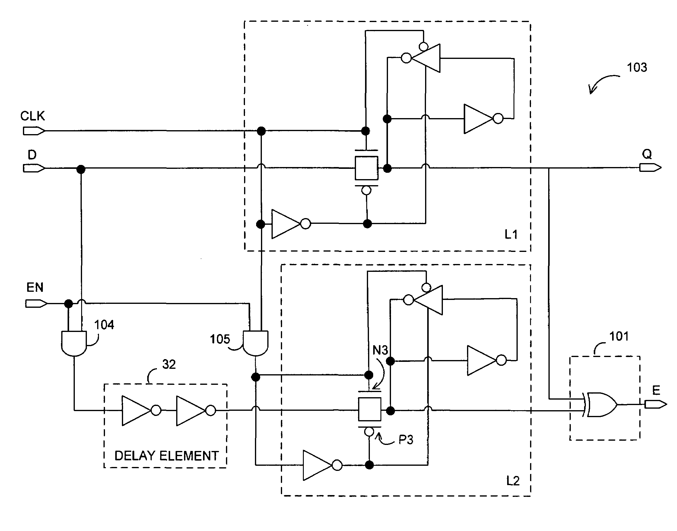
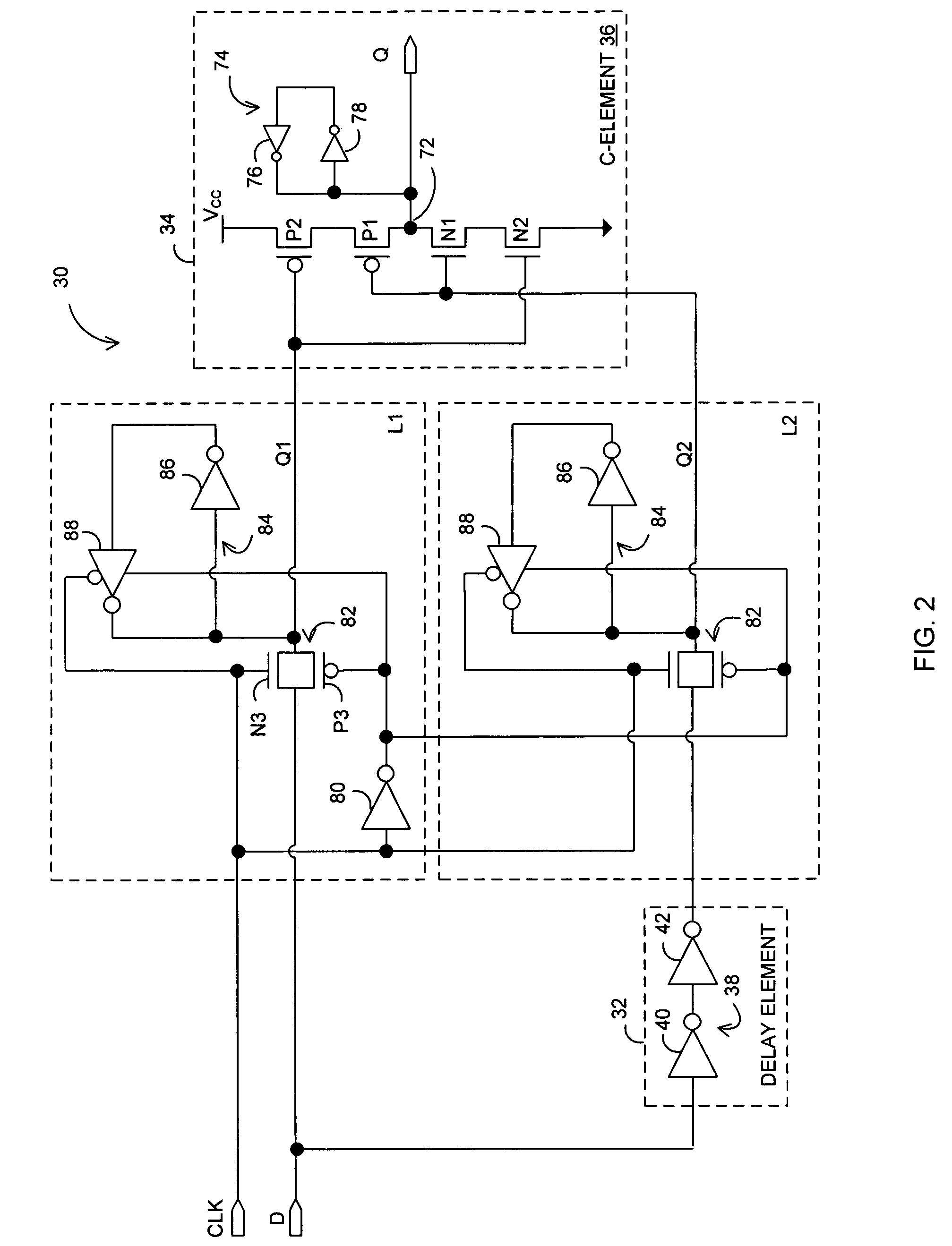
[0019]In the following description, for purposes of explanation, numerous details are set forth in order to provide a thorough understanding of the disclosed embodiments of the present invention. However, it will be apparent to one skilled in the art that these specific details are not required in order to practice the disclosed embodiments of the present invention. In other instances, well-known electrical structures and circuits are shown in block diagram form in order not to obscure the disclosed embodiments of the present invention.
[0020]Various embodiments according to the present invention are directed toward enabling bistable circuits (e.g., latches and flip-flops) with built-in resilience (hardening, self-checking or correcting) to single event upsets (SEUs) occurring in the bistable circuits, while also providing protection against single event transients (SETs) occurring in combinational logic circuits interposed between the bistable circuits. More specifically, in a first...
PUM
Abstract
In one embodiment, an apparatus is provide with a combinational logic circuit to generate a data input signal; a delay element, coupled to the combinational logic circuit, to provide a delayed data input signal in response to the data input signal. Additionally, the apparatus is provided with a system bistable circuit, coupled to the combinational logic circuit, to generate a system bistable signal in response to at least the data input signal; a shadow bistable circuit, coupled to the delay element, to generate a shadow bistable signal in response to at least the delayed data input signal. Further, the apparatus is provided with an output joining circuit, coupled to the system and the shadow bistable circuits, to provide a data output signal in response to the system and the shadow bistable signals.
Description
CROSS-REFERENCE TO RELATED APPLICATIONS[0001]This application is a continuation-in-part of: (a) U.S. patent application Ser. No. 10 / 882,523 (“523”), filed Jun. 30, 2004, now U.S. Pat. No. 7,188,284 entitled “Error Detecting Circuit”; (b) U.S. patent application Ser. No. 11 / 044,826 (“826”), filed Jan. 26, 2005, now U.S. Pat. No. 7,278,074 entitled “System and Shadow Circuits with Output Joining Circuit”; (c) U.S. patent application Ser. No. 11 / 050,996 (“996”), filed Feb. 4, 2005, now U.S. Pat. No. 7,278,076 entitled “System and Scanout Circuits with Error Resilience Circuit”; and (d) U.S. patent application Ser. No. 11 / 128,692 (“692”), filed May 12, 2005, now U.S. Pat. No. 7,373,572 entitled “System Pulse Latch and Shadow Pulse Latch Coupled to Output Joining Circuit”, and this application claims priority to the '523, '826, '996 and '692 applications.BACKGROUND[0002]1. Technical Field[0003]Embodiments of the present invention are related to the field of electronic devices, and in par...
Claims
Application Information
Patent Timeline
Application Date:The date an application was filed.
Publication Date:The date a patent or application was officially published.
First Publication Date:The earliest publication date of a patent with the same application number.
Issue Date:Publication date of the patent grant document.
PCT Entry Date:The Entry date of PCT National Phase.
Estimated Expiry Date:The statutory expiry date of a patent right according to the Patent Law, and it is the longest term of protection that the patent right can achieve without the termination of the patent right due to other reasons(Term extension factor has been taken into account ).
Invalid Date:Actual expiry date is based on effective date or publication date of legal transaction data of invalid patent.
