Measuring circuit for single-event transient pulse width

A single-event pulse and single-event transient technology, applied in the measurement of pulse characteristics, etc., can solve the problems of low measurement accuracy, difficult implementation, and inoperable transistors, and achieve the effect of high measurement accuracy and wide pulse width range.

Active Publication Date: 2012-12-12
BEIJING ZHONGKE XINWEITE SCI & TECH DEV
View PDF4 Cites 13 Cited by
  • Summary
  • Abstract
  • Description
  • Claims
  • Application Information

AI Technical Summary

Problems solved by technology

[0004] 2. Potentially dangerous effects: such as single event latch-up effect, if not controlled, may lead to single event burning of the chip
[0005] 3. Single event hard error effects, such as displacement damage, will make the transistors in the chip completely inoperable
If a traditional oscilloscope or logic analyzer is used to measure the transient pulse width of a single event, the frequency requirements for the equipment are very high, and domestic production is often not possible, while foreign output is prohibited. The test cost is high and the implementation is very difficult.
If the on-chip circuit is used for testing, the existing pulse width measurement method often samples the pulse signal through an external input high-frequency signal, so the capture accuracy is affected by the frequency and performance of the sampling signal, and it is difficult to provide extremely high frequency in actual testing. , the waveform characteristics are very good sampling signal, the measurable range is small, and the measurement accuracy is low

Method used


Image

  • Measuring circuit for single-event transient pulse width
  • Measuring circuit for single-event transient pulse width
  • Measuring circuit for single-event transient pulse width

Examples


Embodiment Construction

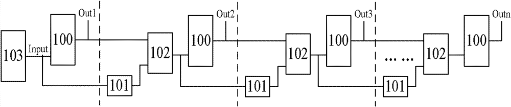
[0026] Such as figure 1 As shown, the single event transient pulse width measurement circuit provided by the embodiment of the present invention includes a single event pulse signal generation circuit (103) and at least one level of measurement circuit (for example, it can be composed of four levels of circuits, of course, according to the needs of measurement, not limited to this).

[0027] Wherein, the bistable circuit 100 directly driven by the single event pulse of the signal to be measured (the single event pulse signal to be measured is generated by the single event pulse signal generation circuit 103 ) constitutes the first stage of the measurement circuit. Starting from the second stage of the measurement circuit, each stage circuit respectively includes a delay circuit 101, a logic gate circuit 102 and a bistable circuit 100; wherein, in the second stage circuit: the input signal of the delay circuit 101 is the signal to be measured. The input signal of the logic gat...


PUM


Abstract

The invention discloses a measuring circuit for single-event transient pulse width. The measuring circuit for single-event transient pulse width comprises a single-event pulse signal generating circuit (103) and at least one measuring circuit. Primary stage of the measuring circuit consists of a bistable circuit. From the second stage, each stage of the measuring circuit comprises a delay circuit, a logic gate circuit and a bistable circuit. In the second stage, input signal of the delay circuit is signal to be measured, input signal of the logic gate circuit serves as output signal of the delay circuit and output signal of the first-stage bistable circuit, and output signal of the logic gate circuit serves as input signal of the bistable circuit in the second stage. From the third stage, the input signal of the delay circuit in each stage serves as the output signal of the logic gate circuit in the previous stage, the input signal of the logic gate circuit serves as the output signal of the current-stage delay circuit and the output signal of the previous bistable circuit, and the output signal of the current-stage logic gate circuit serves as the input signal of the current-stage bistable circuit. The measuring circuit is capable of measuring within a wide pulse width range and is high in measuring precision.

Description

technical field [0001] The invention relates to the technical field of electric pulse width measurement, in particular to a single-event transient pulse width measurement circuit. Background technique [0002] With the development of technologies in aerospace, military and other fields, more and more integrated circuits need to work in radiation environments. The effect of radiation on integrated circuits is mainly divided into two categories: single event effect and total dose effect. After the integrated circuit, the effect produced by the immediate action of the radiation effect. Single event effects can be subdivided into three categories: [0003] 1. Single event soft error effect: including single event reversal effect, single event transient effect, single event multiple reversal effect, etc., which will interfere with circuit nodes in a short time. [0004] 2. Potentially dangerous effects: such as single event latch-up effect, if not controlled, may lead to singl...

Claims


Application Information

Patent Timeline
Patent Type & Authority Applications(China)
IPC IPC(8): G01R29/02
Inventor 宿晓慧毕津顺
Owner BEIJING ZHONGKE XINWEITE SCI & TECH DEV
Why Eureka
Try Eureka