Configuration and method for improving noise immunity of a floating gate driver circuit

a floating gate driver and noise immunity technology, applied in the direction of voltage/current interference elimination, pulse technique, reliability increasing modifications, etc., can solve the problem of difficult to filter out dv/dt noise by dynamic control, inability to achieve dynamic control, and inability to control signal q to turn on or off the power switch pswb>, so as to prevent erroneous triggering of control signal and reduce the time of influence of dv/dt noise

Active Publication Date: 2012-09-13
RICHTEK TECH
View PDF4 Cites 13 Cited by
  • Summary
  • Abstract
  • Description
  • Claims
  • Application Information

AI Technical Summary

Benefits of technology

[0010]Preferably, the loads of the level shifter are dynamically controlled to minimize the time of influence of the dv / dt noise at the time of triggering the control signal.
[0011]According to the present invention, a floating gate driver circuit includes a level shifter with a clamping circuit, a pass element, a bistable circuit and a control logic circuit. The loads of the pass element include two current sources to provide different currents so that the two input terminals of the bistable circuit have different voltage decreasing or increasing speeds at the time of terminating the control signal, to prevent erroneous triggering of the control signal.

Problems solved by technology

The dv / dt noise is introduced to the power supply terminal Vc via the bootstrap capacitor Cb connected between the power supply terminal Vc and the floating node S1, and may lead to an incorrect control signal Q to turn on or off the power switch PSW1 by mistake.
In these arts, the level shifter 12 uses the resistors R1 and R2 as the loads, and the RC response times of the resultant R1C1 network and of the R2C2 network are fixed; therefore, dynamic control is difficult to attain.
The pass element 30, on the other hand, uses the resistors R3 and R4 as the loads, and thus the fixed resistances of the resistors R3 and R4 also make it difficult to filter out the dv / dt noise by dynamic control.
This, however, reduces the flexibility in circuit design.

Method used


Image

  • Configuration and method for improving noise immunity of a floating gate driver circuit
  • Configuration and method for improving noise immunity of a floating gate driver circuit
  • Configuration and method for improving noise immunity of a floating gate driver circuit

Examples


third embodiment

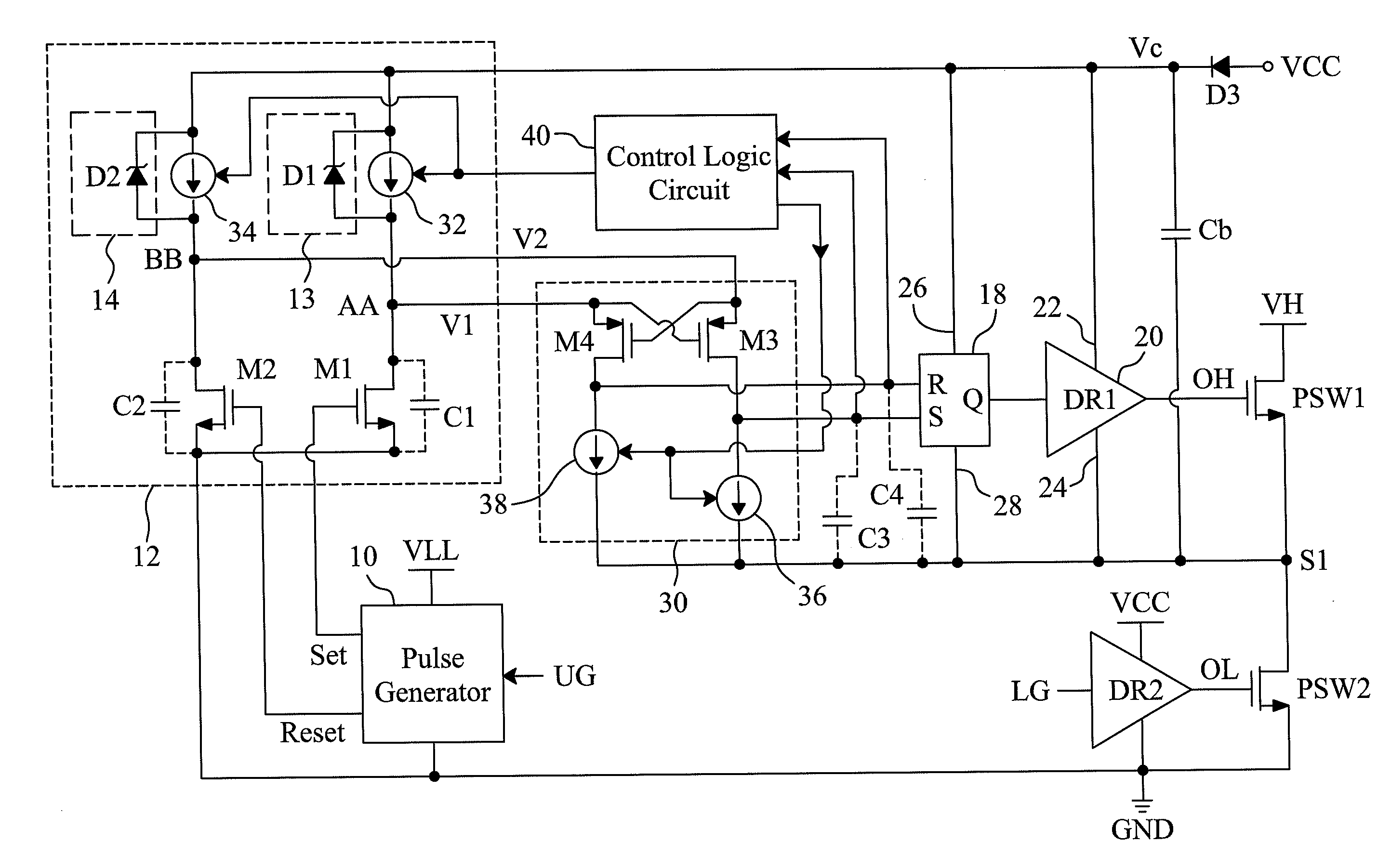
[0032]FIG. 8 is a circuit diagram of a third embodiment according to the present invention, in which the control logic circuit 40 has been dispensed with to reduce the circuit area and cost. In this embodiment, all of the current sources 32, 34, 36 and 38 provide constant currents. However, the current provided by the current source 36 is greater than that provided by the current source 38 so as for the voltage at the set terminal S to decrease at a higher speed than the voltage at the reset terminal R when the control signal Q is terminated.

fourth embodiment

[0033]FIG. 9 is a circuit diagram of a fourth embodiment according to the present invention, which is a modified version of the circuit depicted in FIG. 7. In the circuit of FIG. 9, the resistors Rset and Rreset are used in place of the current sources 36 and 38, respectively, and have a substantially same resistance. In addition, the control logic circuit 40 includes a transconductance amplifier 58 to determine a current Ich according to the voltage at the reset terminal R in order to increase the current at the set terminal S, and consequently the charging speed of the set terminal S increases. Hence, when the control signal Q is terminated, the voltage at the set terminal S will increase faster than the voltage at the reset terminal R. This ensures that the logic state SR=10 will not occur when the control signal Q is terminated, and because of that, the power switch PSW1 will remain off. In a different embodiment, the transconductance amplifier 58 may also be configured to cause...

fifth embodiment

[0034]FIG. 10 is a circuit diagram of a fifth embodiment according to the present invention, which is a modified version of the circuit depicted in FIG. 9. In the circuit of FIG. 10, the control logic circuit 40 includes a switch SW connected between the power supply terminal Vc and the set terminal S. The control terminal of the switch SW is connected to the reset terminal R so that the switch SW is switched responsive to the voltage at the reset terminal R When the control signal Q is terminated, the switch SW is turned on to allow a faster increase in the voltage at the set terminal S than at the reset terminal R. Thus, it can be assured that the logic state SR=10 will not occur when the control signal Q is terminated and that the power switch PSW1 will remain off as a result.


PUM


Abstract

A floating gate driver circuit includes a level shifter, a pass element, a bistable circuit and a control logic circuit, to shift the voltage level of a control signal from a lower one to a higher one. The level shifter or the pass element has loads dynamically controlled by the control logic circuit to filter malfunction caused by dv/dt noise induced by a floating node.

Description

FIELD OF THE INVENTION[0001]The present invention is related generally to a floating gate driver circuit and, more particularly, to a configuration and method for improving noise immunity of a floating gate driver circuit.BACKGROUND OF THE INVENTION[0002]In high-voltage applications such as motors, ballasts, dual-inductor single-capacitor converters (LLC) and cold cathode fluorescent lamp (CCFL), it is required to convert certain logic signals from low voltage to high voltage in order to control the high-voltage components. For example, in a floating gate driver circuit as shown in FIG. 1, control signals UG and LG are used to switch serially connected power switches PSW1 and PSW2 between a high-voltage terminal VH and a ground terminal GND. The direct-current (DC) input voltage VH is very high, maybe up to 300-600V or above, while the control signals UG and LG are generated by a logic circuit with reference to ground, and thus the control signal UG for the high-side power switch PS...

Claims


Application Information

Patent Timeline
Patent Type & Authority Applications(United States)
IPC IPC(8): H03K19/0175
CPCH03K19/018507H03K19/00361
Inventor TSENG, PEI-KAITANG, CHIEN-FULI, KUANG-FENGCHEN, ISAAC Y.
Owner RICHTEK TECH
Why Eureka
Try Eureka