Indicating change to data form

a technology of data form and change, applied in the field of indicating change to data form, can solve the problems of not being able to give a single user a detailed indication of the data field that has been revised, not being able to give a single user a detailed indication, and not being able to quickly identify the data field

Inactive Publication Date: 2009-04-21
MICROSOFT TECH LICENSING LLC
View PDF29 Cites 53 Cited by
  • Summary
  • Abstract
  • Description
  • Claims
  • Application Information

AI Technical Summary

Benefits of technology

[0008]Multiple indicators may also be employed for various levels of data fields. Some nested data fields may be dependent on higher level data fields. If a nested data field is modified, a second indicator may be activated for the nested data field. A primary or secondary indicator may be deactivated if a reset function is activated, or the new data is submitted to a server or database for further action or permanent storage. Deactivation may include overwriting a previous indicator with a blank indicator, or otherwise resetting to an initial state.

Problems solved by technology

However, there is no indication to the user of the data fields that have been revised.
However, this kind of detailed indication is not useful for enabling a single user to visually determine whether he or she had already revised a data field in a data entry form.
While a word processor may indicate that a change was made somewhere in a line of text by simply displaying a vertical bar at a right margin next to the revised line(s) of text, this indication is not sufficiently detailed for a user to quickly identify which data was changed.
Furthermore, changes to multiple data fields may be included in a single line, and based upon a bar appearing in the margin of any line in which a change has been made, a user would not be able to determine the data fields in the line that were modified.
For example, cut and paste operations can fail due to hitting the incorrect key combination for pasting, or attempting to pass too many characters into a field.
Another example is that a user may accidentally delete data from a field while intending to copy it.

Method used


Image

  • Indicating change to data form
  • Indicating change to data form
  • Indicating change to data form

Examples


Embodiment Construction

Exemplary Operating Environment

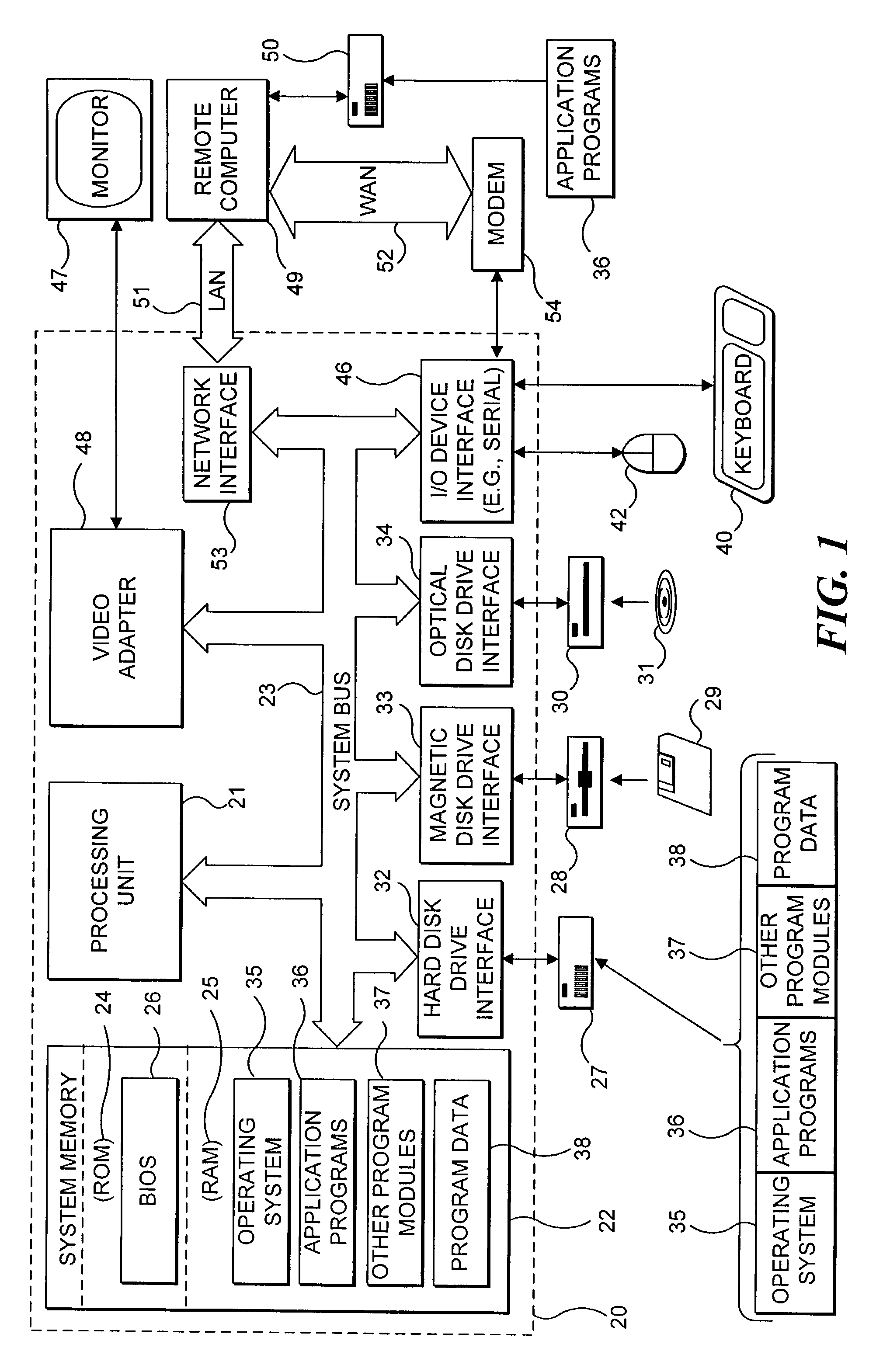
[0015]FIG. 1 and the following discussion are intended to provide a brief, general description of a suitable computing environment for use in implementing the present invention. Although not required, a portion of the present invention will be described in the general context of computer executable instructions, such as program modules that are executed by a PC. Generally, program modules include routines, programs, objects, components, data structures, etc. that perform particular tasks or implement particular abstract data types. Those skilled in the art will appreciate that this invention may be practiced within other computing system configurations including mainframe computers, minicomputers, multiprocessor systems, network PCs, pocket personal computing devices, game consoles, TV set-top boxes, hand held devices, peripheral devices, digital cell phones, industrial control equipment, automotive equipment, aerospace equipment, and other microproces...


PUM


Abstract

Indicating a change to a data field in an electronic data entry form, such as a Web page, database form, or other electronic form. Upon loading an electronic data entry form, an initial content of each data field is stored. User interaction with a data field is detected, and the current content of the data field is compared to the initial content. If the content changes from its initial content, an indicator associated with the changed data field is activated. The indicator may include an icon displayed adjacent to the data field, a change in data field border, font, color, or other sensory characteristic. If a nested data field is modified, a second indicator may be activated for the nested data field. Any indicator may be deactivated if a reset function is activated, or the new data is submitted to a server or database for further action or permanent storage.

Description

FIELD OF THE INVENTION[0001]The present invention generally relates to indicating that a data field has been modified in a data input document such as a form, and more specifically, pertains to providing an indication of the data fields that have been modified since previous data were provided in the data input document.BACKGROUND OF THE INVENTION[0002]Electronic data entry forms typically include a number of data fields into which a user may enter data with a keyboard or other input device. Since the data entered into an electronic data entry form are often changed, it is common to open a form for editing with relation to a specific data record included therein. Previously entered data usually appear in data fields that a user may edit. After revisions or additions have been made to a form, it will typically not be apparent which of the data fields were revised or added.[0003]Previous attempts to track changes in data fields have focused on maintaining an invisible temporary indica...

Claims


Application Information

Patent Timeline
Patent Type & Authority Patents(United States)
IPC IPC(8): G06F17/00G06F3/00
CPCG06F3/04895G06F17/243G06F40/174
Inventor EIZENHOEFER, RICHARD SCOTT
Owner MICROSOFT TECH LICENSING LLC
Why Eureka
Try Eureka