
Method of manufacturing a tuning fork with reduced quadrature errror and symmetrical mass balancing

a manufacturing method and quadrature error reduction technology, applied in the field of tuning forks, can solve the problems of large quadrature error signals, large relative error in output, and inability to manufacture errors, so as to reduce quadrature error, maintain mass balance, reduce quadrature error

Active Publication Date: 2009-04-28
EMCORE INC
View PDF19 Cites 14 Cited by
  • Summary
  • Abstract
  • Description
  • Claims
  • Application Information

AI Technical Summary

Benefits of technology

[0012]Another object of the invention is to provide a tuning fork and method of the above character in which quadrature error is reduced without disturbing tine mass symmetry.
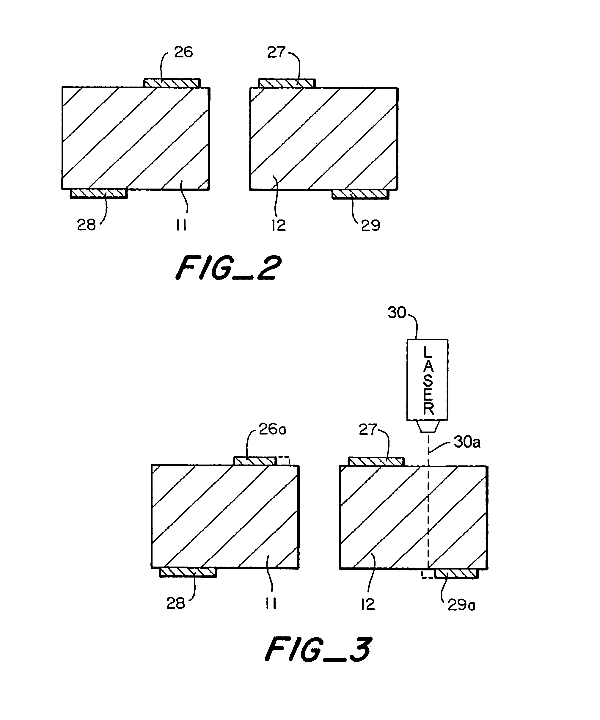
[0013]These and other objects are achieved in accordance with the invention by providing a tuning fork and method in which a pair of elongated tines having front and rear surfaces are disposed symmetrically about an axis, and balancing masses on the front surface of one tine and on the rear surface of the other tine are trimmed to reduce quadrature error and also to maintain mass balance between the tines.

Problems solved by technology

A common problem in such devices is that minute variations in fabrication of the tuning fork can cause relatively large errors in the output.
These fabrication errors can arise due to faceting in crystalline materials and / or errors in the cross-sectional geometry of the tines (i.e., the tines are not perfectly rectangular).
The quadrature error signals are often much larger than the desired full scale output of the sensor.
However, it also has a significant disadvantage in that the two tines become unbalanced in mass.
This imbalance causes the moments of the tines to be unequal so that a net lateral force is transmitted to the base of the tines and, ultimately, to the fork mount and its surroundings.
This coupling of the tuning fork to the surrounding environment degrades the performance of the sensor, particularly if this environment includes any elements with mechanical resonances at or near the drive frequency of the fork.
While this technique may result in a balanced fork, it is not useful in tuning fork rate sensors because it does not provide any adjustment of the quadrature output, and the quadrature offset would, in general, remain quite large.

Method used


Image

  • Method of manufacturing a tuning fork with reduced quadrature errror and symmetrical mass balancing
  • Method of manufacturing a tuning fork with reduced quadrature errror and symmetrical mass balancing
  • Method of manufacturing a tuning fork with reduced quadrature errror and symmetrical mass balancing

Examples


Embodiment Construction

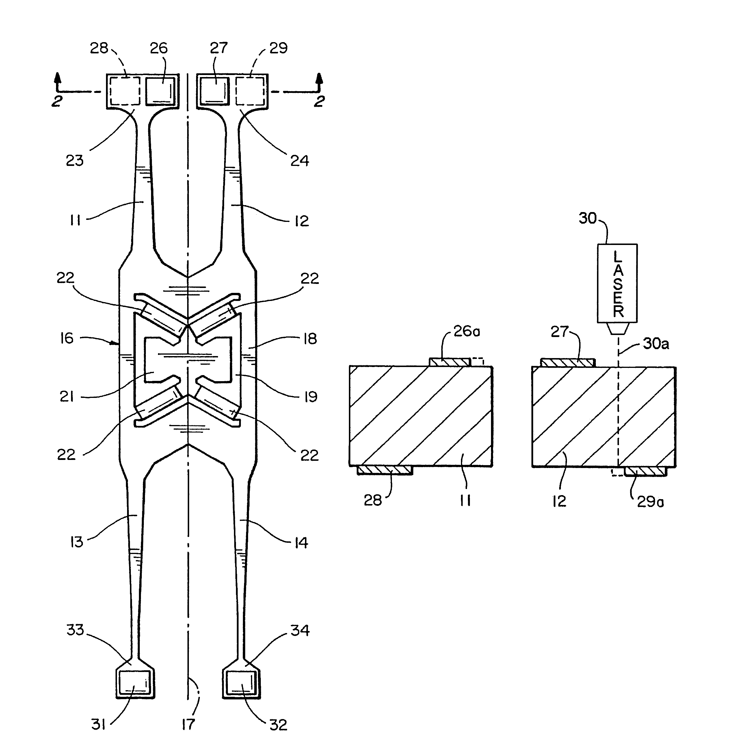
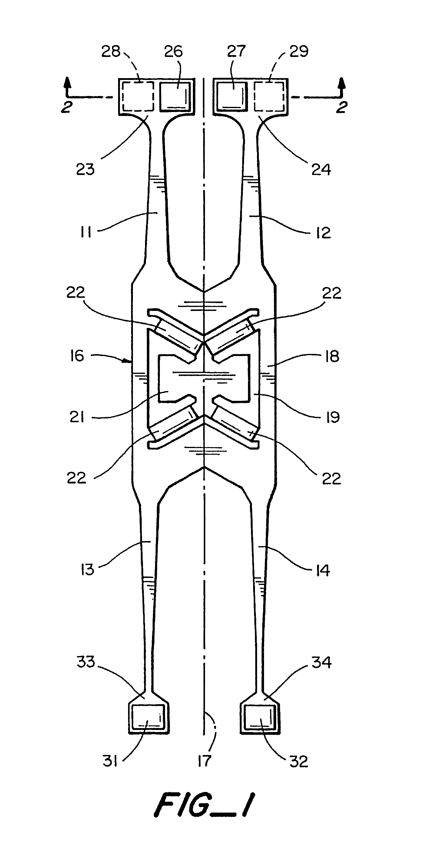
[0017]As illustrated in FIG. 1, the tuning fork has a pair of drive tines 11, 12 and a pair of pickup tines 13, 14 which extend in opposite directions from a central body or base 16 and are disposed symmetrically about the longitudinal axis 17 of the device. The body includes a frame 18 which surrounds a central opening 19, with a mounting pad 21 within the opening connected to the frame by relatively thin bridges 22. The tuning fork is formed as a unitary structure of a piezoelectric material such as quartz. Drive and pickup electrodes (not shown) are mounted on the tines in a conventional manner.

[0018]The free ends of drive tines 11, 12 include areas of increased lateral dimension 23, 24, with balancing masses 26-29 on the upper and lower surfaces of the tines in those areas. The masses are offset laterally of each other, with masses 26, 27 being positioned closer to the inner edges of the tines on the upper surfaces of the enlarged areas and masses 28, 29 being positioned closer ...


PUM

PropertyMeasurementUnit
massaaaaaaaaaa
drive mode frequencyaaaaaaaaaa
transparentaaaaaaaaaa

Abstract

Tuning fork and method in which a pair of elongated tines having front and rear surfaces are disposed symmetrically about an axis, and balancing masses on the front surface of one tine and on the rear surface of the other tine are trimmed to reduce quadrature error and also to maintain mass balance between the tines.

Description

BACKGROUND[0001]1. Field of Invention[0002]This invention pertains generally to tuning forks for use in rate sensors and, more particularly, to a tuning fork and method in which mass balance is maintained when quadrature error is reduced.[0003]2. Related Art[0004]Tuning fork rate sensors make use of the Coriolis effect to sense rotation. The tuning fork is driven to oscillate in a drive move in which the tines oscillate in a plane with roughly equal and opposite amplitudes. Under rotation, the tines experience a Coriolis acceleration proportional to the velocity of the tines and in a direction orthogonal to the drive motion. In a double-ended tuning fork, the orthogonal acceleration excites a pickup mode of vibration which causes both the driven set of tines and the other (pickup) set to vibrate out of the plane of the device. In quartz rate sensors, this out-of-plane vibration is detected piezoelectrically in a manner well known in the art.[0005]A common problem in such devices is ...

Claims


Application Information

Patent Timeline
Patent Type & Authority Patents(United States)
IPC IPC(8): H04R7/02G01C19/5607H01L41/08H03H9/24
CPCG01C19/5607H03H9/2494Y10S29/901Y10T29/49156Y10T29/42Y10T29/49005
Inventor KNOWLES, STUART J.MOORE, ROBERT H.
Owner EMCORE INC
Learn More