Device for positioning and affixing magnets to a magnetic yoke member of a motor

a technology of magnetic yoke and magnet, which is applied in the direction of dynamo-electric machines, automatic control devices, cores/yokes, etc., can solve the problems of difficult precise positioning of magnets on that yoke, cost and cumbersome, and the inability to operate the gluing of magnets on the magnetic yoke member almost impossible to manually

Inactive Publication Date: 2009-04-28
ETEL SA
View PDF5 Cites 19 Cited by
  • Summary
  • Abstract
  • Description
  • Claims
  • Application Information

AI Technical Summary

Benefits of technology

[0008]An example embodiment of the present invention may provide the ability to position then affix, e.g., by gluing, magnets to a magnetic yoke member of an electric motor, e.g., to form the magnetic path of a linear motor, without being disturbed by the magnetic attraction this yoke exerts on the magnets, e.g., in the facility where the motor is built or at the site where it will be assembled and / or used, and without the use of a costly and / or cumbersome device.
[0015]An aspect of example embodiments of the present invention is, therefore, to vary the distance between the magnets held by a nonmagnetic support in the device and, on the one hand, a magnetic part of the device that holds the magnets in place on this support and, on the other hand, the magnetic yoke member of the motor intended to receive those magnets. It is thus possible to vary the magnetic forces of attraction present, the magnetic attraction of the yoke on the magnets being initially compensated by a greater magnetic attraction arising from the device itself during the initial steps of the method serving to position the magnets, which may allow for great precision in positioning magnets on the yoke and may not require complex tooling.
[0020]The arranging and maintaining step may include increasing retention of the magnets in position on the nonmagnetic support by attractive effect of the magnetic element after arranging the magnets by bringing together the nonmagnetic support and the magnetic element.
[0022]The arrangement may be adapted to displace the nonmagnetic support and the magnetic element in a direction of the magnetic yoke member to increase the magnetic attraction of the magnetic yoke member on the magnets.
[0023]The arrangement may be adapted to displace the magnetic element to separate the magnetic element from the nonmagnetic support without reduction of a separation between the magnets and the magnetic yoke member.

Problems solved by technology

When these magnets are brought in proximity with the magnetic yoke member, the force of attraction created between the yoke and the magnets may make precise positioning of the magnets on that yoke difficult except on an assembly line having special equipment that may be costly and cumbersome.
The operation of gluing magnets on a magnetic yoke member is almost impossible manually.
Gluing magnets on a motor yoke member may present a major problem whenever that yoke is an integral part of the equipment frame in which the motor is integrated.
This solution may have the disadvantage of requiring a significant investment and a great deal of time to glue all the magnets.
Moreover, the tooling used for this horizontal installation is fragile and ill suited to gluing techniques.
If, in this case, gluing of the magnet occurs without problems, because of the absence of magnetic attraction, this solution may nevertheless require a very considerable investment, e.g., with respect to the magnetization tooling, and also may require lengthy cycle time for each magnet.

Method used


Image

  • Device for positioning and affixing magnets to a magnetic yoke member of a motor
  • Device for positioning and affixing magnets to a magnetic yoke member of a motor
  • Device for positioning and affixing magnets to a magnetic yoke member of a motor

Examples


Embodiment Construction

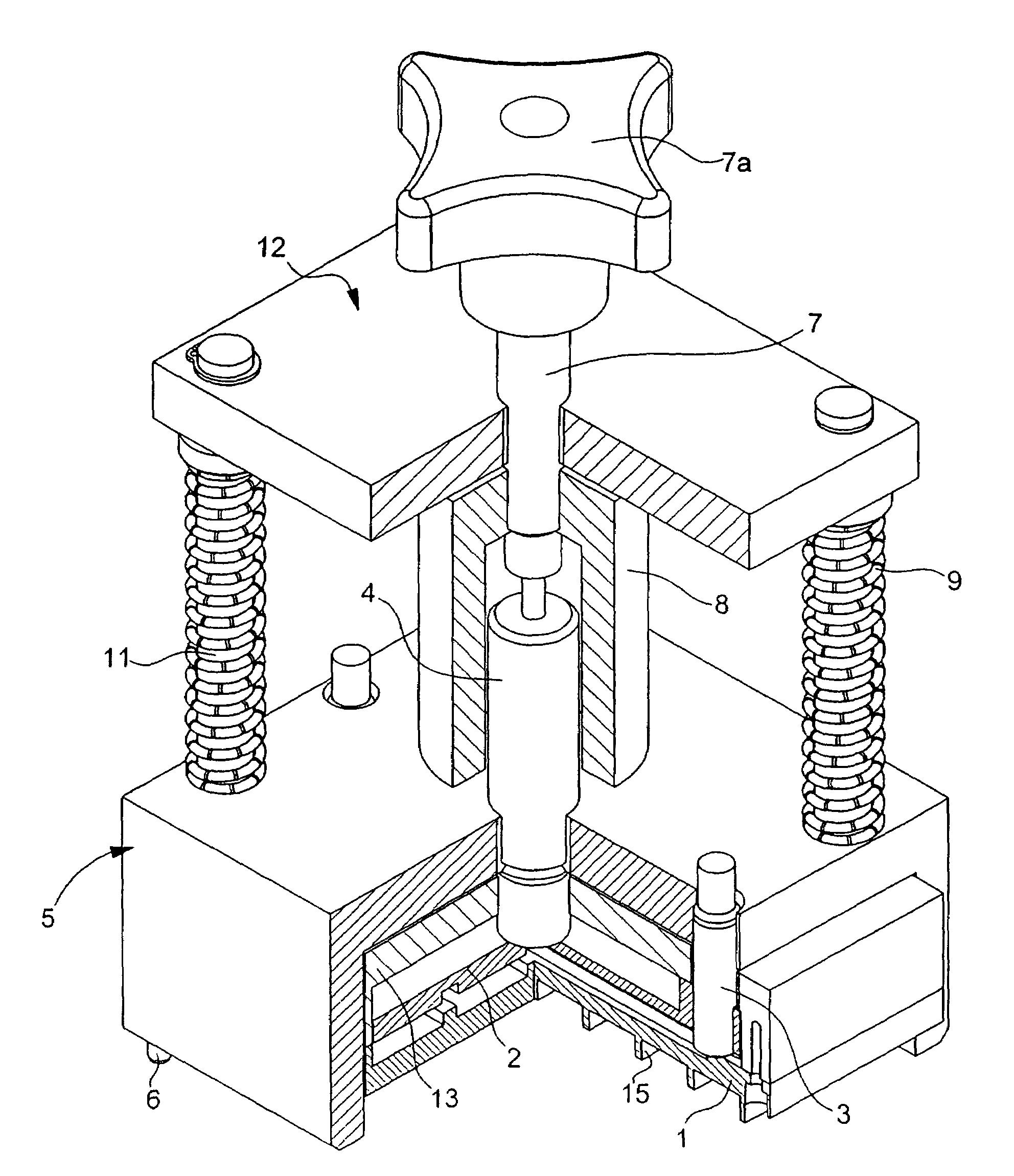
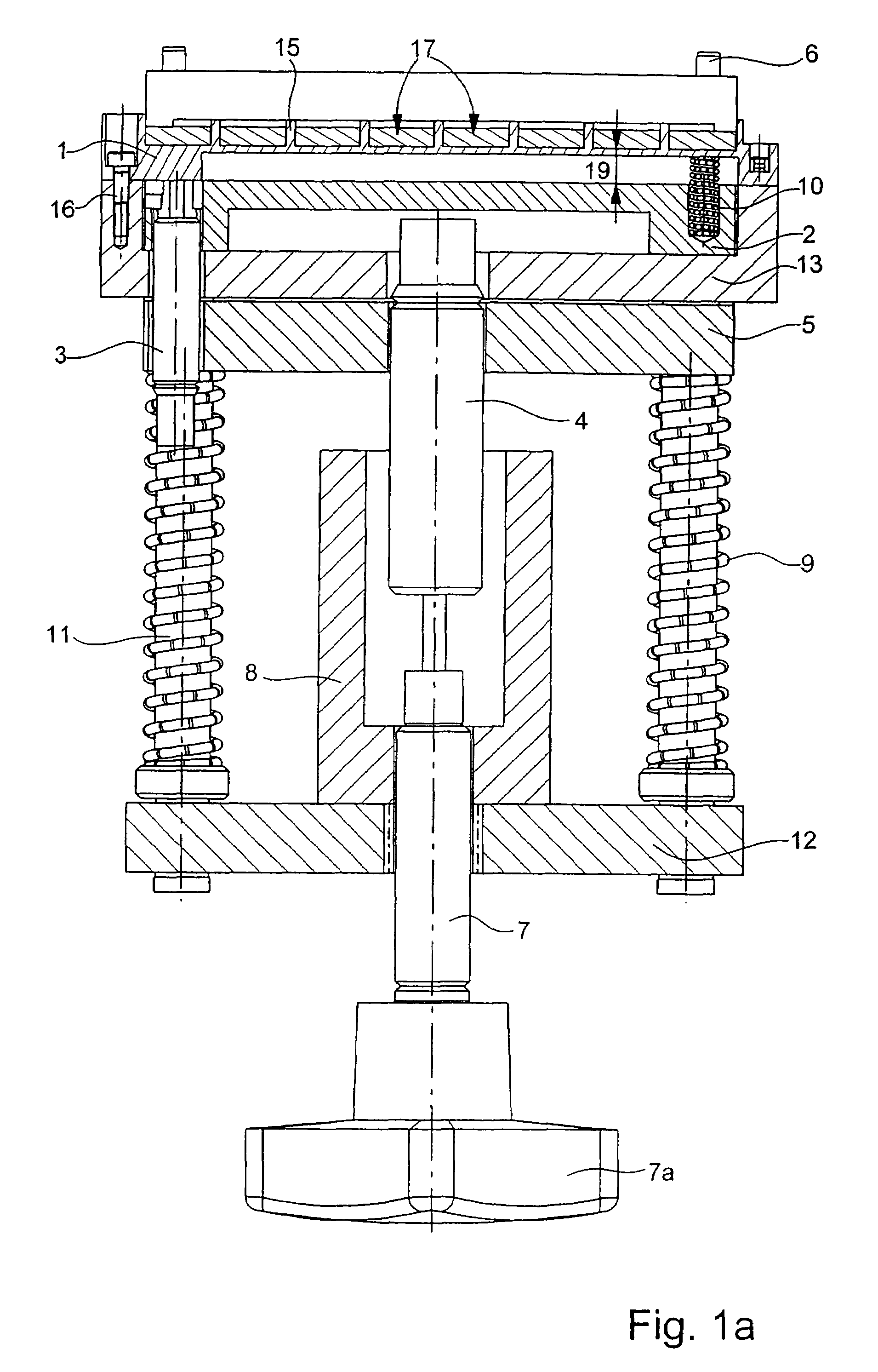
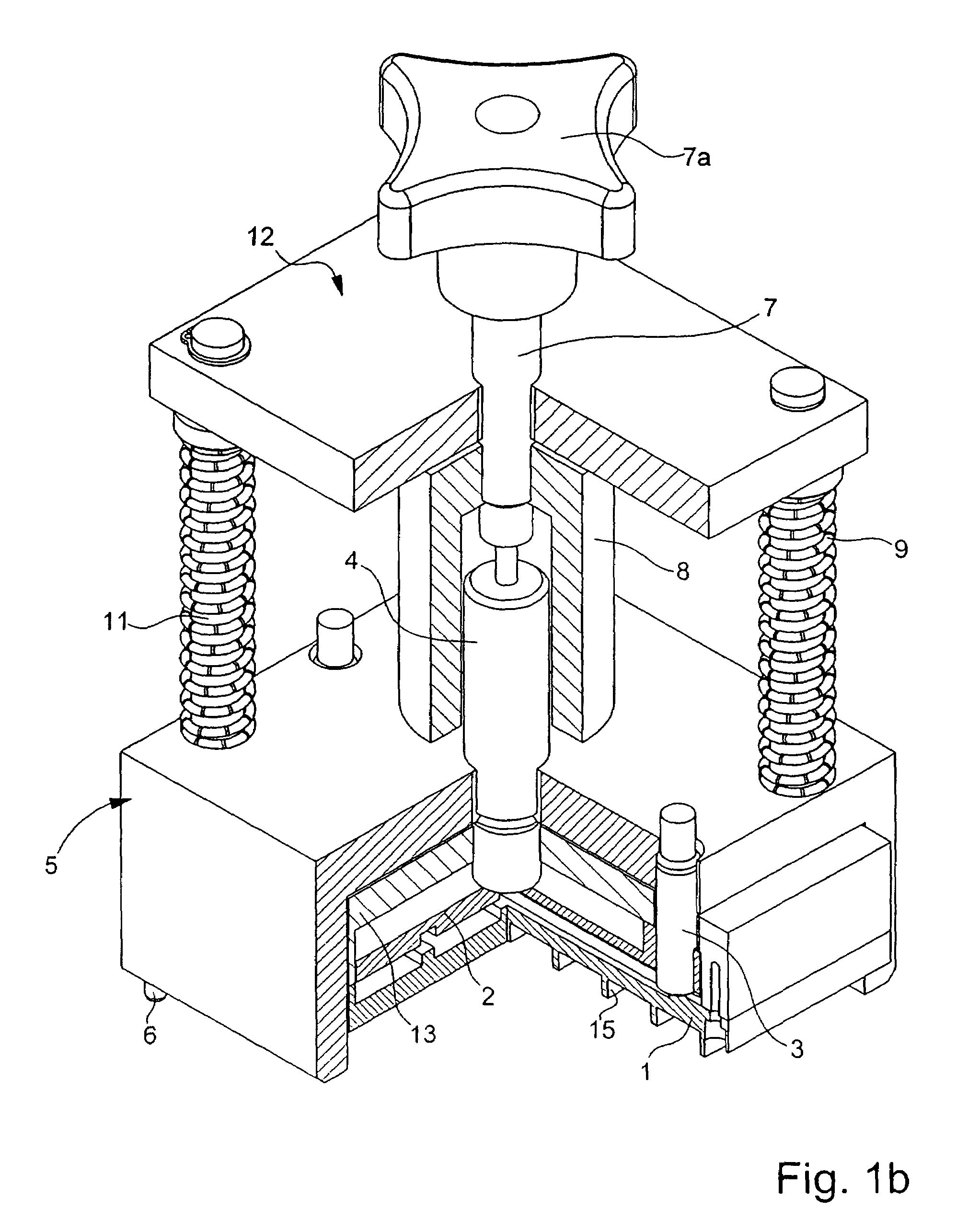
[0041]Referring to FIGS. 1a, 1b, and 1c, which illustrate the device in various complementary manners, it is illustrated that the device includes four parts. A first part, forming the chassis of the device, includes upper plate 12, four vertical rods 11, and magnetic element 2 connected to this upper plate 12 by the rods 11. A second part includes housing 5, which, as described below, rests on the magnetic yoke member of the motor and is maintained in position by pins 6 during the positioning of the magnets above the motor yoke. A third part includes nonmagnetic support 1 and cap 13 on which nonmagnetic support 1 is attached by bolts 16. Magnetic element 2 is located between support 1 and the upper part of cap 13. The fourth part includes screw 7 with its tightening knob 7a, the screw being connected to sleeve 8 extending the screw vertically and having its upper part attached to screw 7. This screw 7 is screwed into internal or screw threads in upper plate 12.

[0042]Rods 11 travel f...


PUM

PropertyMeasurementUnit
distanceaaaaaaaaaa
distanceaaaaaaaaaa
shapeaaaaaaaaaa

Abstract

A device for positioning and affixing magnets on a magnetic yoke member of an electric motor includes: a nonmagnetic support for receiving the magnets; a magnetic element for holding the magnets in position on the nonmagnetic support arranged on the other side of the nonmagnetic support with respect to the magnets, the attraction exerted by this element on the magnets greater than that exerted by the magnetic yoke member during positioning of the device with respect to the yoke; a device for varying the magnetic forces present, whereby the magnetic attraction of the magnetic yoke member and / or the magnetic element on the magnets may be varied such that the magnetic force of attraction exerted by the yoke on the magnets becomes greater than that exerted by the magnetic element on them, thus provoking transfer of the magnets to the yoke.

Description

CROSS-REFERENCE TO RELATED APPLICATIONS[0001]The present application claims priority to Application No. 00813 / 04, filed in Switzerland on May 7, 2004, which is expressly incorporated herein in its entirety by reference thereto.FIELD OF THE INVENTION[0002]The present invention relates to a method and device for positioning and affixing magnets on the magnetic yoke member of a motor.BACKGROUND INFORMATION[0003]A conventional linear motor includes a stator provided with permanent magnets and a mobile element provided with at least one excitation coil. Such a linear motor, for example, is described in European Published Patent Application No. 0 871 284, where it is used in an X-Y table. The stator includes a magnetic yoke member on which are positioned a series of juxtaposed magnets of alternating north-south polarity. It is important that the magnets be carefully positioned in parallel to one another and that a constant pole pitch be maintained. These magnets are, in general, affixed b...

Claims


Application Information

Patent Timeline
Patent Type & Authority Patents(United States)
IPC IPC(8): H02K15/00H02K1/18H02K1/28H02K15/03H02K21/12
CPCH02K15/03Y10T29/49009Y10T29/49879Y10T29/53143Y10T29/49012Y10T29/49076Y10T29/53083Y10T29/4981Y10T29/13
Inventor MOREL, JEAN-PIERRE
Owner ETEL SA
Why Eureka
Try Eureka